Graphics window Graphics area |

|

|

|

|

|
||
|
Graphics window Graphics area |
|
|
|

|

|

|
Graphics window
Graphics area
|
Graphics window Graphics area |
|
|
|
|
|
||
|
Graphics window Graphics area |
|
|
|
|
|
|
|
|
||
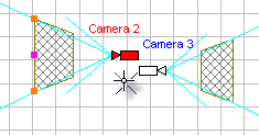
The graphics area contains two projections of the current layout.
A thick black line designating the ground in vertical (upper) projection parts these two projections.
You can hide any projection using the tools Hide horizontal projection ![]() and Hide vertical projection
and Hide vertical projection ![]() or using the corresponding items of the Main menu.
or using the corresponding items of the Main menu.
Main work is carried out as a rule in the horizontal projection. Vertical projection is used only in some cases. In the Vertical projection cameras and constructions are shown relative to the ground without taking into account base heights of layers and base heights of cameras.
When drawing a camera in the vertical projection of the Graphics window, its height will be equal to the sum of the camera installation height, the base height of the camera and the height in the parameters of the group to which the camera belongs, if the Base heights of cameras in vertical projection checkbox is checked.
The background color in the graphics area can be changed.
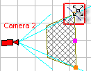
Editing state ( active state of cameras )
Graphical editing state of active camera
Wheel Mouse is particularly convenient when working in the graphics window. Using the Wheel mouse you can change drawing scale with the simultaneous zooming in the drawing sections pointed by the cursor.
If Ctrl is not pressed at changing the scale, then the scale changes roughly which is convenient at navigation. If Ctrl is pressed, the scale changes with the less step which is convenient for the precise drawing positioning before printing or saving.
The Step and direction of scaling can be changed in wide range via Scale factor in the Options box.
You can move the drawing by pressing and holding down the mouse wheel (or the middle button). If Ctrl is not pressed, the entire drawing is dragged, if Ctrl is pressed, the horizontal projection is dragged only.
You can move drawing using horizontal and vertical scroll bars.
When Alt is pressed, it is possible to move drawing in the Graphics window using arrow keys and change scale using plus and minus keys irrespective of the input focus.
There is an opportunity of quick navigation with the help of text markers.
Since all the constructions in VideoCAD are made by two clicks, but not by pressing and release the mouse button, so it is very convenient to combine constructions with quick navigation.
To show all cameras and constructions, use item of the Main menu or Pop-up menu: Scale>Show all.
|
The graphics area allows to use 2 coordinate systems:
In case of Fixed coordinate system, the origin of coordinates does not vary when changing the active camera. The origin of coordinates is displayed by two icons
In case of the coordinate system attached to the active camera, the origin always coincides with the active camera location. It is convenient when studying its view area. A grid is fixed to the origin of coordinates, and the counting of the cursor current coordinates in the status bar starts from the origin.
The Status bar on the left end shows the origin type: CAM - active camera, ORG - specified origin. By clicking on this area, you can call the pop-up menu to select the type of origin and set the origin point on the layout.
|
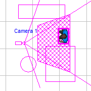
The graphics area may contain the following objects:
|
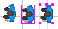
All the objects except for the backgrounds and titles can take one of the following states:
You can change object's state with the help of the Select/Edit To hide objects use the Hide Main menu item. To switch the active camera to the graphical editing state use the Edit active camera
|
|
If there are selected objects on the layout, the Selection Editing Panel appears. On the panel, you can set parameters for all selected objects at once.
Selected objects can be filtered by many parameters using the Selection Filter.
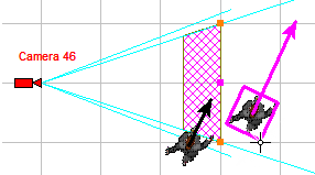
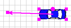
The length of the velocity vector of a 3D model in the normal state is inversely proportional to the frame rate of the active camera. Thus we can see how many times the moving 3D model gets into the frame of the active camera.
An object may be not available for selection if it is on an inaccessible layer. A camera may be not available for selection if it belongs to an inaccessible group of cameras or is on an inaccessible layer.
|
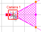
![]() Editing state ( active state of cameras )
Editing state ( active state of cameras )
To switch illuminator to editing state double-click on its center.
An object may be not available for selection if it is on an inaccessible layer. A camera may be not available for selection if it belongs to an inaccessible group of cameras or is on an inaccessible layer.
|
See also: Layers - Hidden;
|
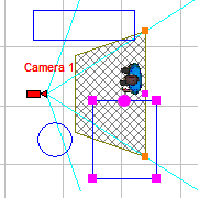
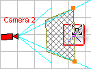
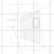
![]() Graphical editing state of active camera
Graphical editing state of active camera
The Active camera can take the Graphical editing state . In this case the objects in the horizontal projection rotate so that the direction of the camera lens main optical axis becomes parallel to a screen plane, and the bounds of active camera view area are marked with lines of double thickness.
The lower and upper bounds of view area displayed by horizontal green lines. If the active camera has pixel density displayed, the horizontal red line indicates height of pixel density measurement.
The graphical editing state enables a detailed analysis of view area using the test object, in the vertical projection it becomes possible graphical calculation of depth of field, study of the vertical projection of the built-in IR illumination zone, pixel density analysis and field-of-view sizing at any point of view area. In the graphical editing state the Test object is visible in the 3D Video.
In the graphical editing state of the active camera, selection and rotation of the active camera is blocked to prevent displacement of the background, constructions and cameras relative to each other on other layouts.
To switch active camera to the graphical editing use the Edit active camera
|