Camera Geometry Sensor and Lens |

|

|

|

|

|
||
|
Camera Geometry Sensor and Lens |
|
|
|

|

|

|
Camera Geometry
Sensor and Lens
|
Camera Geometry Sensor and Lens |
|
|
|
|
|
||
|
Camera Geometry Sensor and Lens |
|
|
|
|
|
|
|
|
||
The Sensor and Lens panel can be called up by the
On the panel you can set:
In addition to specifying the lists, the tools on the Sensor and Lens panel can improve accuracy of modeling the shape of the view area, by taking into account:
If an error about 20-30% is acceptable when modeling the shape and size of the view area, then you can neglect these tools, limiting yourself to traditional tools for specifying the image sensor format, lens focal length and the number of active pixels in the Camera Geometry box.
|
|
See before: Image Sensor and Active area of image sensor
On the Image sensor panel you can set the size and aspect ratio of the image sensor or size of active area of the image sensor. Size and Aspect ratio boxes duplicate the Image sensor size box on the Camera geometry window, but allow you to enter the size and aspect ratio in different boxes.
In the Size box you can specify the image sensor size by any of the following ways:
This traditional way of setting the image sensor size can be unaccurate for modern cameras.
If you enter a format which does not exist in the list, the box turns yellow, and the Image sensor size will be calculated by VideoCAD.
See more: Specifying image sensor size through its diagonal and aspect ratio
See more: Direct specifying image sensor side sizes
In the Format box you can specify the active area side sizes of the image sensor in millimeters horizontally and vertically separated by asterisk, in the form of W*H. For example: 4.8*3.6;
See more: Direct specifying active area side sizes of the image sensor
You can set the size of the Image sensor by the interval between pixels (Pixel Interval) in microns, for example "17mcm". This is useful for thermal cameras.
In the Aspect ratio box you can specify the aspect ratio of the image sensor in the form of W:H. For example: 16:9 or 4:3.
To save changes click OK or close the box. To cancel changes click Cancel.
See also: Specifying active area size of the image sensor/
|
See before: Image Sensor and Active area of image sensor
On the Image sensor's active area panel you can specify parameters of active area of the image sensor, involved in forming the image.
In the List of resolutions box, you can specify a list of possible resolutions of the active camera, in pixels. For the convenience of filling the list, you can call the drop-down form
See details: List of resolution
In the Aspect ratio box displays the aspect ratio of the active area of the image sensor. It is identical with the Aspect ratio of the output image of the camera.
See more: Specifying the Aspect ratio of output image
Set Aspect ratio from pixels - calculate the Aspect ratio as the ratio of the numbers of pixels horizontally and vertically. This rule is fair for the most of CCTV cameras. If the checkbox is checked, then the Aspect ratio of the active camera will be recalculated with each change of resolution in pixels. Changing the Aspect ratio leads to a change in the shape and size of the view area.
In the Crop box you can set the crop factor - the ratio of cropping active area size of the image sensor when the active area does not touch the edges of the image sensor. In other cases Crop=1. The Crop factor can be set as a vulgar fraction (separated by slash) or a real number. For example 4:3 0.67 or 16:9 720/1080. If the crop factor is not specified, it is taken to be unity.
See more: Specifying the crop factor
The Calculator icon
The Horiz., Vert. and Diag. boxes display sizes of the active area of the Image sensor, which are used in modeling the camera. These sizes are calculated based on the size and aspect ratio of the image sensor, as well as the aspect ratio of the output image.
In the boxes, you can directly type any sizes of the active area of the image sensor in millimeters. In this case, the aspect ratio of the active area will be defined by the ratio of its sizes. The Aspect ratio box will show Custom. By this method, you can specify an arbitrary aspect ratio of the image and camera angles.
Below you can see the dynamic image showing the position and relative sizes of the active area on the image sensor (aqua color) subject to the selected aspect ratios and crop factor.
Examples of images of image sensor of real cameras:
To save changes click OK or close the box. To cancel changes click Cancel.
See also: Specifying active area size of the image sensor/
|
On the Lens panel you can see:
Lens focal length - the box duplicates the similar box in the Camera geometry.
Calculated view angles are calculated from the sizes of active area of image sensor and the lens focal length.
In the List / Range box you can set a list of possible values or the range of the lens focal length. For the convenience of filling the list, you can open the drop-down form
See more: List/Range
To save changes click OK or close the box. To cancel changes click Cancel.
|
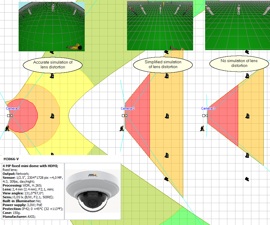
See before: About Lens distortion.
As a rule, taking into account lens distortion is relevant for lenses with a focal length of less than 4mm. For long focus lenses, the distortion is usually can be neglected. In cases requiring precision, compare the real view angles (from the camera manufacturer's specifications or obtained by practical measuring) with the calculated view angles displayed in this box. If the angles differ by more than several degrees, the distortion of the camera lens may be noticeable. You can simulate distortion and evaluate its impact on your task.
In the combo box, you can choose how to simulate lens distortion.
In the Options box, you can switch the way of distortion modeling in the entire project at once.
You can set the distortion modeling method in the camera model parameters via the List/Range of Lens focal lengths field.
When modeling lens distortion, the lens focal length box uses green bold underlined font. When modeling lens distortion in a simplified way, the lens focal length box uses bold blue underlined font.
There are two ways to set lens distortion in VideoCAD:
1. Using any two of three real view angles (horizontal, vertical, diagonal) and aspect ratio
If camera specification contains 2 real view angles and the resolution in pixels is known, then this method is the most convenient. The aspect ratio can be calculated automatically from the pixel resolution. If any 2 view angles and resolution in pixels are set, then an error of size of the active area of image sensor and the lens focal length has only little effect on the result of modeling lens distortion.
2. Using one real view angle (horizontal, vertical, diagonal), lens focal length and the size of the active area of the image sensor
If the camera specification contains only one real angle of view (usually horizontal), then the exact value of the Lens focal length and the size of the active area of the image sensor are required to simulate the lens distortion.
See: Specifying active area size of the image sensor
If you set real angle values too differed from calculated angles or set other inconsistency, then the boxed will colored in Red and (or) the view area will be corrupted..
You can control simulation of distortion for all cameras in the Options box > Miscellaneous > Lens distortion > Simulate distortion. There, in the Options box, you can change the discretization accuracy of distortion simulation.
Attention! Changing the lens focal length or the format / size of sensor at fixed real angles causes view area corruption and requires changing the real angles. Therefore, it is advisable to enable modeling distortion after a preliminary selection of proper lens to increase precision of modeling. To set the actual distortion angles for multiple lenses or for varifocal / ZOOM lenses, use the List/Range string.
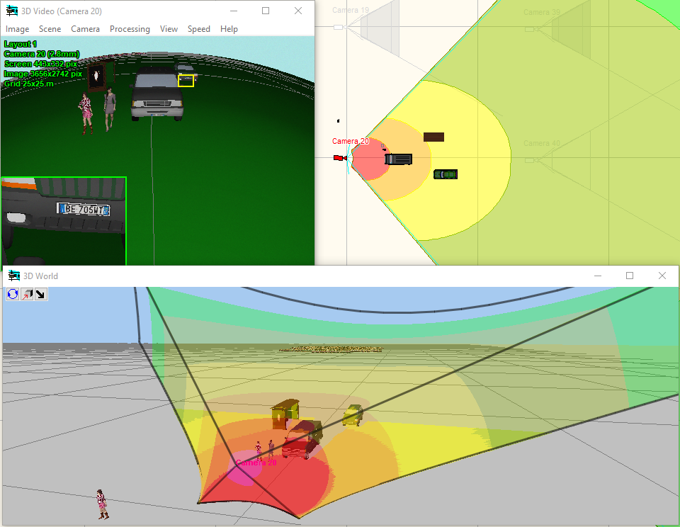
Under the influence of the lens distortion the view area becomes more complicated, it sometimes becomes infinite . To limit the distance of view area drawing use the Maximum distance of drawing view area.
Accurate distortion modeling increases the execution time of many operations and increases the requirement for computer speed. With a large number of cameras in a project, it is recommended to accurately model distortion only when necessary. For most cameras, it is recommended to use Simplified Distortion Modeling.
To save changes click OK or close the box. To cancel changes click Cancel.
See also:About lens distortion Modeling lens distortion, Measuring real view angles of a camera, Specifying active area size of the image sensor
|