Modeling Multisensor cameras |

|

|

|

|

|
||
|
Modeling Multisensor cameras |
|
|
|
|

|

|
Modeling Multisensor cameras
|
Modeling Multisensor cameras |
|
|
|
|
|
||
|
Modeling Multisensor cameras |
|
|
|
|
|
|
|
|
||
Multisensor cameras allow to cover a large space with high pixel density. Compared to Fisheye cameras, Multisensor cameras make more efficient use of the available pixels to display the surrounding objects. In fact, multisensor camera is a bundle of several modules Image sensor + lens. These modules can produce individual images or one common image glued from images from modules. Many multisensor cameras allow you to direct modules independently, as well as install different lenses on the modules.
VideoCAD provides tools for modeling multisensor cameras with independent and linked modules, as well as matrix multisensor cameras with modules located in several lines. Any position of a multisensor camera in space (rotation, tilt, rotation around its axis) can be simulated.
See more: Multisensor camera
Below we will look at modeling a simple multi-sensor camera with independent modules.
|
|
You can simulate multisensor cameras in VideoCAD in 2 ways:
1. Simulation of individual modules of a multisensor camera as separate cameras, combined into the Camera group.
This method is convenient if the modules of the multisensor camera produce individual images and are treated in the project as separate cameras.
Set the Camera group parameter Combined.
You can set the cameras in the group the Multisensor icon ![]() or hide icons of all cameras except one.
or hide icons of all cameras except one.
However, the cameras of the group will remain separate cameras. The combined picture from a group of cameras can be obtained only on the Monitor window or glued manually.
2. Using positions for modeling modules of a multisensor camera.
This method is closest to the essence of a multisensor camera.
Positions are copies of camera positions and parameters that are ideal for modeling individual modules.
For even greater convenience, VideoCAD offers a tool for automatic positioning multisensor camera modules.
Problem
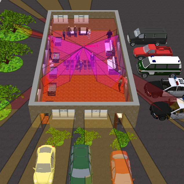
There is the AXIS P3717-PLE camera. The camera is installed on the 3m high in the center of a rectangular room 10 * 20 m. It is necessary to control the room in the height range of 0.5-2 meters.
It is required to obtain view area projection, the view area in 3D, distribution of pixel density and image model from this camera.
Camera parameters according to the manufacturer's specifications, important for modeling the view area:
| • | Number of modules - 4. |
| • | The possibility of free direction of the modules - Yes. |
| • | Parameters of each module: |
| • | Number of pixels - 1920x1080. |
| • | Image sensor size - 1 / 2.8 ". |
| • | Varifocal lens 3-6mm. |
Order of work
1. Create a camera by clicking the New camera ![]() button. In the camera creation dialog select the Camera icon
button. In the camera creation dialog select the Camera icon ![]() multisensor.
multisensor.
Assigning a special icon is optional. In the future, you can change the icon in the ![]() Camera list window.
Camera list window.
If the camera model is present in the database of real camera models, then there is no need to enter the camera parameters manually, just select the model from the Active Camera Model list or in the Table of Camera Models. The manual input of parameters is described below, for a case this camera model is not available in the database of real models.
Set camera parameters in the
|
|
2. Model a room 10 * 20 meters with 3 meters of height by the tool
See Example
Place the camera in the center of the room.
Set the far bound of the view area at the inner edge of the room.
Enable modeling shadows by selecting |
|
2. Open the Position of active camera / Multisensor window by the
Switch to the Multisensor tab.
Mark the Multisensor camera checkbox.
Select 4 in the Sensors in line combobox.
Select Order of sensor - Tilted. The tilt of the positions is determined by the tilt of the active (parent) camera.
Select Angle of sensors 360/4 = 90 degrees to evenly distribute 4 modules in all directions.
Select Additional lines (up/down) - 0/0. No additional lines of sensors.
Set the View area upper and lower bounds for the multi-sensor camera.
the View area upper and lower bounds for the multi-sensor camera are set independently of the view area bounds of the parent camera, that allows you to construct projections (sections) of the view area of linked and matrix multisensor cameras in any range of height, regardless of the directions of individual modules.
Click the Add positions as sensors
The active camera will automatically be copied to the created 4 positions.
If necessary, you can hide the parent camera by checking the Hide parent camera checkbox.
On the projection you can be seen that there are small blind sectors between the positions. They turned out because we did not take into account the distortion of the lenses. View angles of real camera will be slightly larger due to the distortion and the view areas of the modules will intersect without dead sectors. Camera specification contains values of the real angles so we could model it precisely.
Editing position (in space) of a multisensor camera consists of two steps: 1. Editing the position (in space) of the active camera. 2. Click on the Update sensors
To edit sensors as positions, switch to the Positions tab.
To edit a position:
When copying a position to the parent (active) camera, the current parameters of the parent camera will be overwritten. If you want to save the parameters, then create an additional hidden position to store the parent camera.
|
|
2. Open the
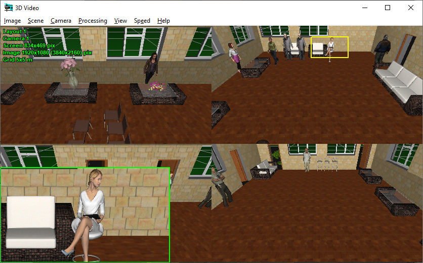
Right-click on the image in the 3D Video - the Image parameter panel will appear. Switch to the Panoramic tab.
Using the switch Positions> Show You can choose to show:
In the Images per row combobox , you can choose how many images will be in one row of the multi-image screen. The number of rows is calculated automatically.
To see details of the image in real camera resolution:
To save the multi-image in real camera resolution of 3840 * 2160:
Saving with high resolution may take some time.
The model of multisensor cameras allows to simulate high resolution in PiP, images with real camera resolution, motion blur, animated images and camera sensitivity. You can print multi-images to the PDF report and load to the Monitor window, as well as normal images.
|
|
See also: Fisheye cameras, Positions of active camera