Modeling cameras with Fisheye lens |

|

|

|

|

|
||
|
Modeling cameras with Fisheye lens |
|
|
|

|

|

|
Modeling cameras with Fisheye lens
|
Modeling cameras with Fisheye lens |
|
|
|
|
|
||
|
Modeling cameras with Fisheye lens |
|
|
|
|
|
|
|
|
||
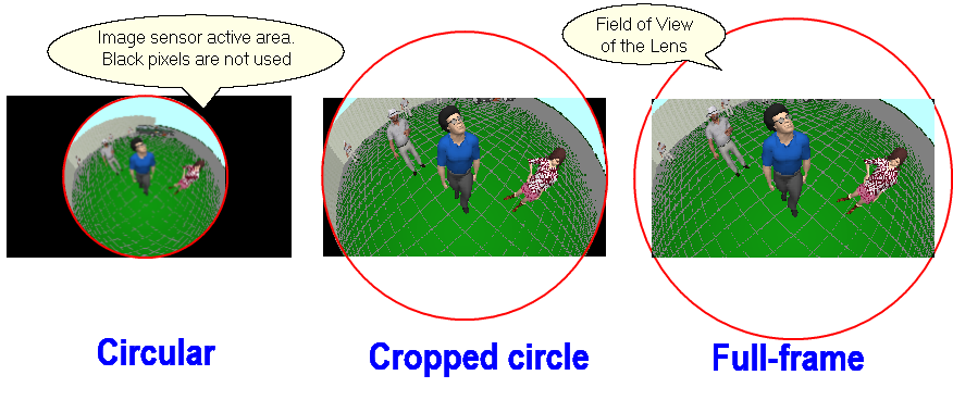
The view area of Fisheye cameras is a part of sphere. Field of view is projected by a Fisheye lens in the form of circle.
Depending on the ratio of sizes of this circle and the active area of the image sensor, there are 3 types of FishEye lens:
See more Fisheye
See also about Fisheye lenses in Wikipedia
Problem
There is a camera BOSCH FLEXIDOME IP panoramic 6000. The camera is mounted on a bracket at 3m height at a distance of 10 meters from a wall of 10 meters height. Camera is pointed down.
It is required to obtain a model of the control area, the distribution of the pixel density and image models from this camera.
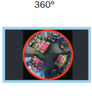
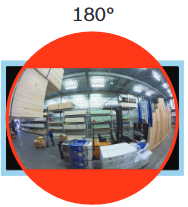
The camera has 2 versions:
|
NDS-6004-F360E |
NDS-6004-F180E |
|
|
|
|
Circular FishEye lens |
FishEye lens of Cropped circle |
|
Pixels:2640 x 2640 |
Pixels:3640 x 2160 |
|
View angles: 180° (H) x 180° (V) |
View angles: 180° (H) x 93° (V) |
Order of work
1.1 Create a camera by clicking the New camera
A special icon is not obligatory. In the future it will be possible to change the icon in the
|
If the camera model is present in the database of real camera models, then there is no need to enter the camera parameters manually, just select the model from the Active Camera Model list or in the Table of Camera Models. The manual input of parameters is described below, for a case this camera model is not available in the database of real models.
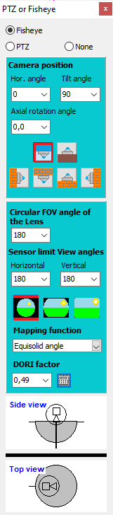
2.1 Open the Camera geometry
The most important parameter that determines the image resolution of Fisheye cameras, is the number of pixels of the image sensor.
Since the image sensor is rectangular in shape and view area of the camera is projected into a circle, not all pixels are involved in image formation. In VideoCAD the number of physical pixels on the sensor horizontally and vertically are required. The number of pixels involved in the formation of the image will be calculated by VideoCAD.
Lens focal length and Image size at image processing have no affect on the image resolution of Fisheye cameras.
2.2 Click on the
|
![]() 3. Placing the camera on the layout
3. Placing the camera on the layout
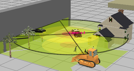
3.1 Place the camera on the layout. At the distance of 10 meters from the camera create a wall of 10 m height using the
3.2 In the Camera geometry
To limit too big size of the view area projection use the Maximum distance of drawing view area box in the Camera geometry
|
![]() 4. Adjusting pixel density visualisation
4. Adjusting pixel density visualisation
4.1. Assign to the camera a Pixel density pattern to visualize the pixel density. For this purpose open the
Pattern criterion of pixel density for Fisheye cameras must be based on the pixel density (Pixel per meter (Pixel per foot), Pixel for object), but not on the field of view size. Criterion Field-of-view height, % of Field-of-view for object are not suitable to Fisheye cameras, because of Fisheye cameras have not a rectangular field of view.
4.2. Enable and adjust the pixel density visualization in the Graphics window. In the popup menu of the In the popup menu of the In the popup menu of the
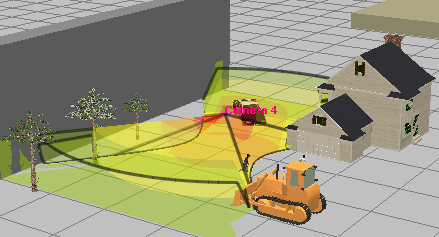
As a result we will see in the Graphics windows the pixel density distribution of the camera on the height specified in the Pixel density pattern assigned to the camera.
The maximum drawing distance of view area projections is determined by the Maximum distance of drawing view area.
|
![]() 5. Selecting the DORI Factor from DORI Values
5. Selecting the DORI Factor from DORI Values
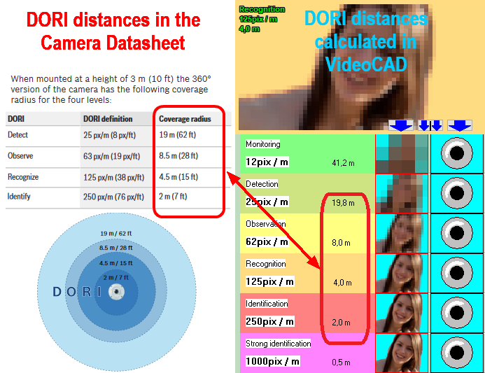
There are DORI (Detection,Observation,Recognition,Identification) values in the specification.
In order for the pixel density distribution in VideoCAD to be exactly the same as in the camera specification, it is necessary to select the DORI factor to the maximum match of distances in the DORI table and in the Pixel density box. To calculate the DORI factor clock on the Calculate
For the NDS-6004-F360E model, the optimal DORI factor value = 0.53.
|
![]() 6. FishEye camera in the 3D World window
6. FishEye camera in the 3D World window
6.1 Open the Using the navigation in the 3D space, we can see pixel density at any point on the surfaces around the camera, as well as we can detect invisible areas shaded by other objects.
6.2 Close the 3D World window.
|
![]() 7. FishEye camera in the 3D Video window
7. FishEye camera in the 3D Video window
7.1 Open the
Right-click on the 3D Video window to display the Image parameter panel and switch to the Panoramic tab.
Choose the switches: Positions> Show> Camera and Fisheye> Show> Full image
The 3D Video window will display the full image.
7.2 If you move the mouse cursor over the 3D Video window with the left mouse button pressed, the camera will change direction following the cursor. Moving the cursor while pressing Shift will cause the camera to rotate around its axis.
7.3 Enable the Image Processing if it is disabled. If PiP mode is enabled, you can select areas for viewing in real resolution by clicking on the image by the middle mouse button (wheel).
|
![]() 8. Getting an image in real resolution
8. Getting an image in real resolution
8.1 Mark Image> Real frame size in the Main menu of the 3D Video window.
8.2 Save the image to a file with the real 5MP resolution by selecting Image> Save As in the Main Menu of the 3D Video.
Saving in high resolution takes time, wait until the end of the process.
8.3 Clear Image> Real frame size in the Main menu of the 3D Video window.
|
![]() 9. Obtaining dewarped frame fragments in real resolution
9. Obtaining dewarped frame fragments in real resolution
9.1 Mark the switch Fisheye>Show>Dewarped image fragment (on the Image parameter panel). By directing the camera on points of interest on the scene, we can see with what resolution these regions will be displayed by our camera.
9.2 Place Let's try to change the lens focal length and make sure that only the size of the field of view is changed. Resolution of the image will remain constant.
9.3 Pan, tilt and rotation of the camera around its own axis, made in the usual way does not affect the position of the Fisheye camera. By rotation the camera in the usual way, you can view images from the Fisheye camera in different directions in the 3D Video. In this case, the view area will be limited by the Circular angle of the lens. Beyond this limit the image is cut.
You can change the Lens focal length, thereby changing the field of view size, but the image resolution in the 3D Video will always be maintained equal to the calculated resolution of the Fisheye camera. If the calculated resolution is worse, the resolution of the 3D Video will be artificially reduced. If the calculated resolution is better, then the PiP mode will be launched in the 3D Video. The Image line in the Titles displays a virtual number of pixels for correct simulation of the resolution.
Distortion of a Fisheye camera images in the 3D Video is not modeled. The simulated resolution is exact only at the center of the frame. Towards the edges of the frame the actual resolution is worse than simulated. The smaller the view angle, the more accuracy of simulating resolution on the edges of the frame. For a more realistic model of the image, turn on modeling of compression and smoothing, or set the actual resolution of the lens (for accurate simulation the lens resolution you also need to specify the correct size of the image sensor).
|
![]() 10. Modeling multiple Fragments using Positions
10. Modeling multiple Fragments using Positions
10.1 Open the Positions of active camera window by Click
10.2 Now go back to the 3D Video window, right-click on the window, open the Image parameter panel, switch to the Panoramic tab, and select the Positions> Show> Cam+positions (show camera and positions). Switch Fisheye> Show> Dewarped image fragment should be marked.
You will see the camera positions you set in the screen division mode. In each cell, the image resolution is limited by its own calculated value.
|
![]() 11. Other FishEye camera simulation options
11. Other FishEye camera simulation options
With the model of Fisheye camera VideoCAD can simulate real camera resolution with PiP, saving image with real camera resolution, motion blur, animated images and modeling camera sensitivity.
|
See also: Fisheye cameras