Measuring resolution of camera (lens) |

|

|

|

|

|
||
|
Measuring resolution of camera (lens) |
|
|
|
|

|

|
Measuring resolution of camera (lens)
|
Measuring resolution of camera (lens) |
|
|
|
|
|
||
|
Measuring resolution of camera (lens) |
|
|
|
|
|
|
|
|
||
Problem
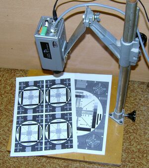
There is an image of the test chart EIA 1956, made by equipment under test (camera+lens+DVR). It is necessary to determine equipment resolution in LPH at contrast loss of 10%.
The test chart EIA1956 in full resolution allows to measure resolution up to 1600 LPH. To measure higher resolution you can also use the test chart EIA1956, but it should not occupy the entire frame, but a part of the frame. For example, if the table will occupy by the area of a quarter of the frame (half the vertical and half of horizontal sizes), the range of measured values of resolution will be doubled.
By making measurements with the same camera, but with different lenses, we can compare resolution of the lenses. Lens resolution is very important for megapixel cameras.
We can measure resolution with a given drop of contrast as well as drop the contrast at a given resolution. |
|
To perform the measurements you need the software CCTVCAD Lab Toolkit (visit http://cctvcad.com ).
Solution
1. Open the Image analyzer from CCTVCAD Lab Toolkit.
2. Click Load in the upper left corner of Image analyzer and select image file.
3. For conveniences it is recommended to increase image size in 2 times. To do this open the Processing tab, enter two times larger sizes on the Image size panel and click Apply.
4. Open the TV lines tab.
5. Click vertical wedge area of the test chart with lines corresponding to the minimal resolution (100-200 LPH). Record peak-to-peak amplitude of signal in the area of minimal resolution.
The peak-to-peak amplitude of signal can be seen on the oscillogram under the image.
6. Move the cursor with pressed mouse button to the side where the wedge becomes narrow up to the moment when the peak-to-peak amplitude of signal from the wedge makes 10% from the signal amplitude at minimal resolution.

7. Determine resolution according to the place of analyzing line on the test chart.
In case when resolution is close to the maximal possible one at specified image size and camera aperture corrector works, determining the point of the contrast loss of 10% could be difficult. Image pixel beating and chart lines beating as well as image digitization hinder from it. This problem refers equally to all ways of resolution measurement.
Using CCTVCAD Lab Toolkit we can measure resolution of separate colors.