|
|


|

|

|

|

|
|||
|
General information on VideoCAD 13 Professional |
|
|
|

|

|

|
|
|
|
|
|
|
|
|
|||
|
General information on VideoCAD 13 Professional |
|
|
|
|
|
|
|
|
||
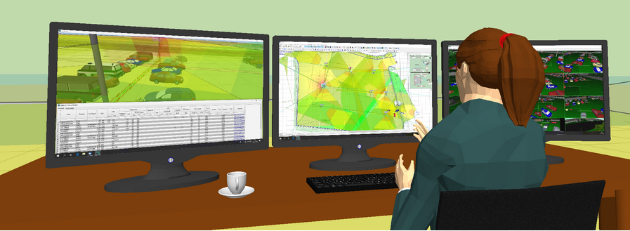
VideoCAD is a multifunctional tool for professional video surveillance system design, modeling parameters of video image and video equipment.
VideoCAD allows even the beginners to use the new opportunities appearing to be hard to obtain without it due to the complexity of calculations and therefore not being used even by the skilled engineers of CCTV.
VideoCAD practically boosts the quality of CCTV design to a new level which appears to be beyond any competition with those lacking the program.
Two VideoCAD versions are offered:
| • | VideoCAD Professional - the most powerful, professional version with many unique tools. |
| • | VideoCAD - a basic version with restrictions that are acceptable in most projects: |
| • | No more than 70 cameras in one project; |
| • | No export to 2D DXF DWG formats (to AutoCAD); |
| • | No export to 3D COLLADA format (to SketchUP); |
| • | No accurate lens distortion modeling, only simplified lens distortion modeling; |
| • | No simulation of camera sensitivity; |
| • | No animation. |
The main features of VideoCAD 13 Professional:
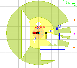
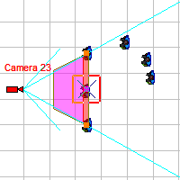
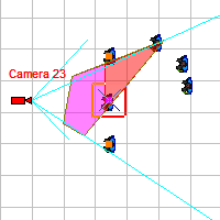
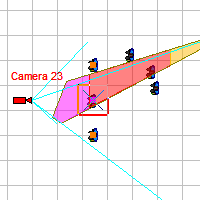
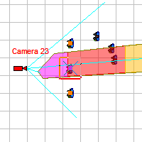
Calculating geometric parameters of camera view area in any camera position.
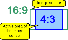
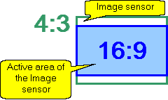
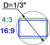
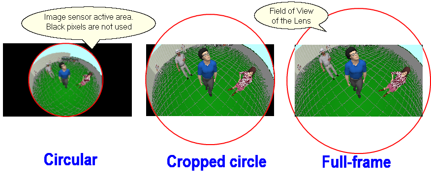
Calculating size of the active area of the image sensor in dependence of the aspect ratio of the image sensor and the aspect ratio of the output image of the camera.
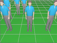
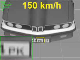
Calculating horizontal projection sizes of person detection, identification and license plate reading areas.
Calculating Depth of Field of each camera of the project.
Calculating the image size on display of any object in camera view area in percentage of display size, pixels and millimetres (inches in case of Imperial format).
Calculate length and electric parameters of cables.
Calculate light power and illumination produced by illuminators.
|
Use 2D Graphics window with CAD interface. Use a lot of 2D/3D constructions and CAD tools, line types, font types, snaps, up to 10 layouts in each project, unlimited number of layers.
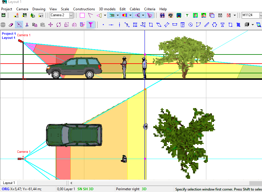
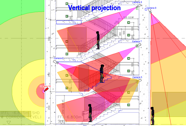
2D modeling in horizontal and vertical projections is possible.
Display on the 2D layout results of calculations: view area projections, person detection and identification areas, depth of field limits, test object, cables and luminaries.
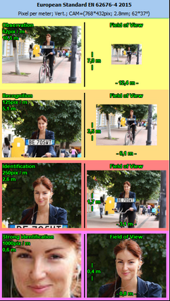
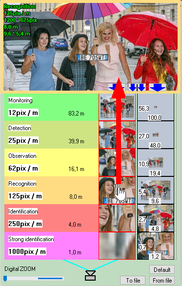
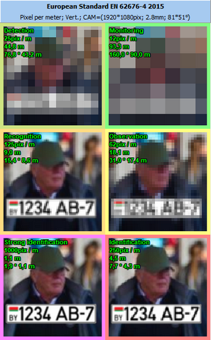
Display by separate colors and hatch styles different regions of pixel density and field-of-view size. There are prepared pixel density patterns according to the following criteria: Home Office Scientific Development Branch; Home Office Guidelines for identification; P 78.36.008-99, Australian Standard AS4806: Closed Circuit Television, European Standard EN50132-7, ISO/IEC 19794 Biometric data interchange formats, EN 62676-4 2015, Johnson's criterion for thermal cameras.
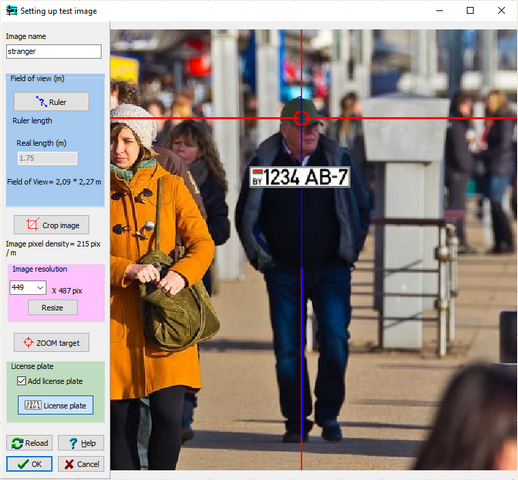
The Edit Test Image Tool to quickly create test images for pixel density tables from custom photos. Using any photos allows you to take into account specifics of real goals and scenes.
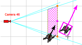
Construct the horizontal projection of camera control areas including shadows from obstacles on the scene.
Choose the best camera positions and calculate control areas in 360 degrees.
Modeling camera rotation around the main optical axis.
Modeling lens distortion. Modeling influence of the lens distortion on view area shape, on view area projection shape and pixel density distribution.Correct modeling wide-angle lenses with strong distortion.
Simulating distortion of varifocal / ZOOM lenses with a complex dependence of distortion on the focal length.
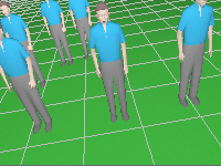
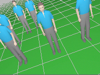
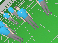
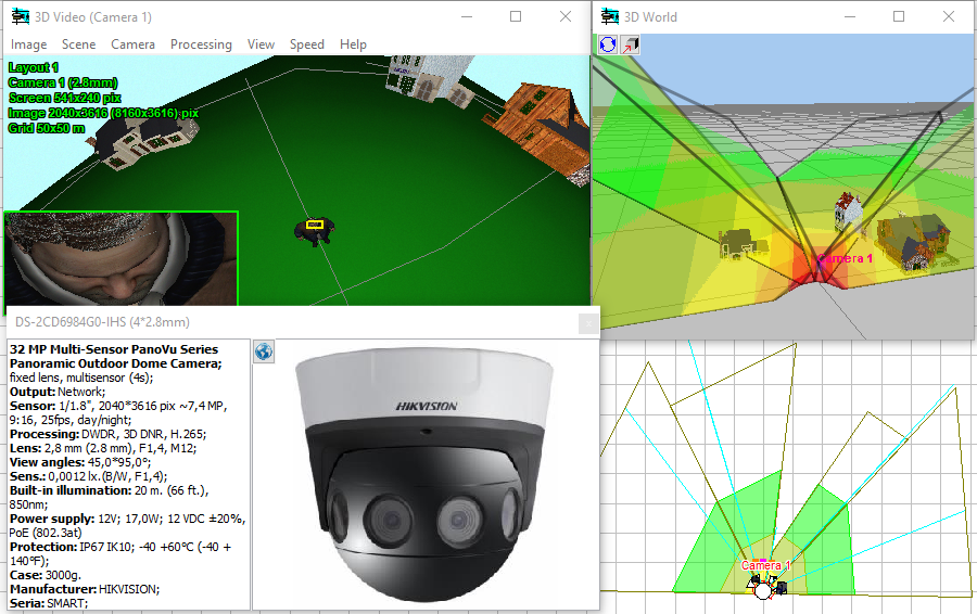
Quick assessment of the view of any 3D model through any camera, depending on relative position of the camera and the 3D model in space.
|
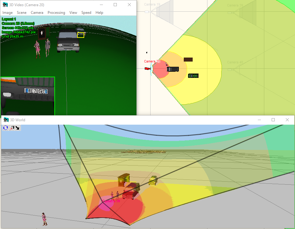
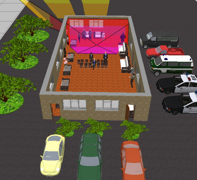
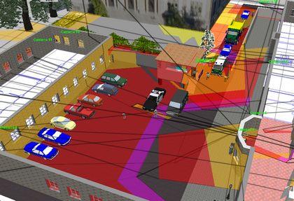
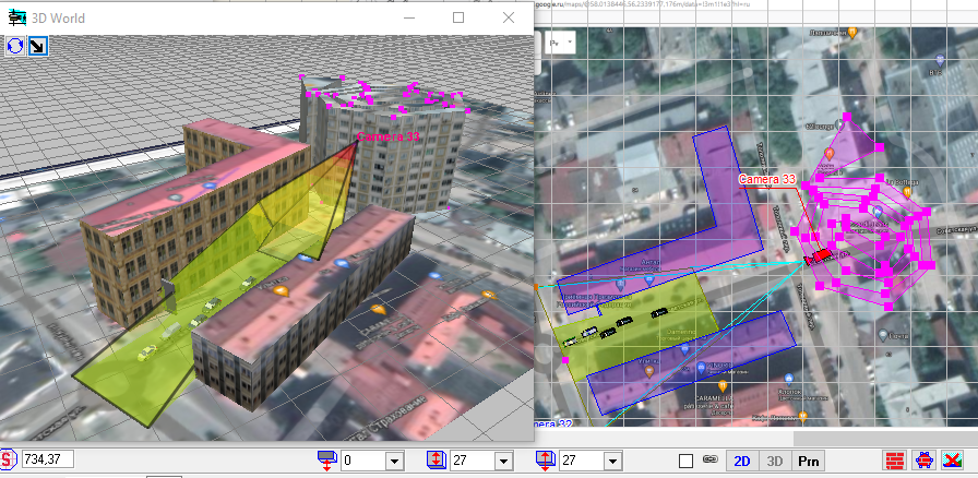
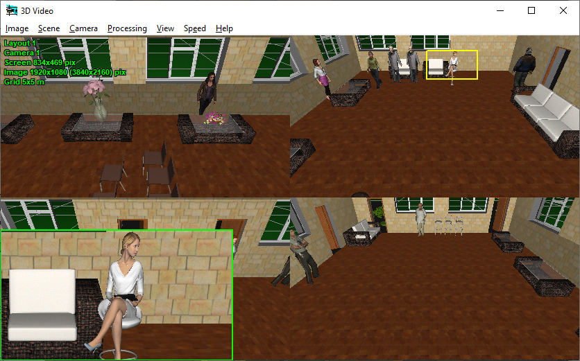
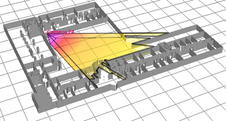
VideoCAD has special 3D World window with standard tools for 3D navigation (Orbit, Move, ZOOM, Walk, Look around, Zoom frame). With the help of the window you can observe the layout in 3D representation. You can work on the project in usual 2D projections and watch it in 3D. You can "walk" on the floors of 3D models of buildings and study every detail.
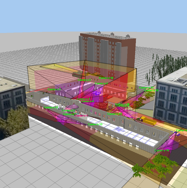
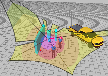
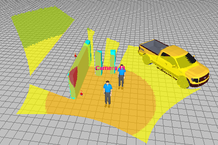
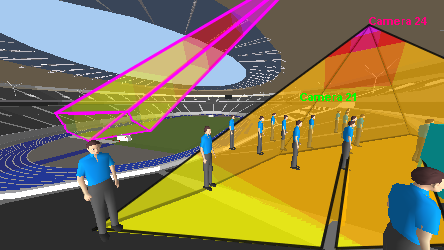
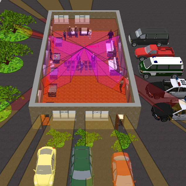
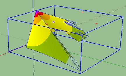
3D visualization of the camera view area surface taking into account pixel density, shadows, lens distortion.
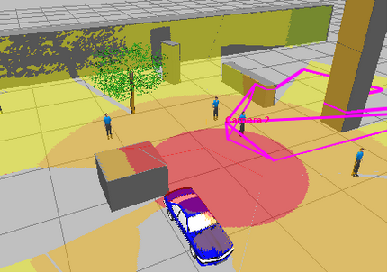
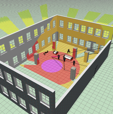
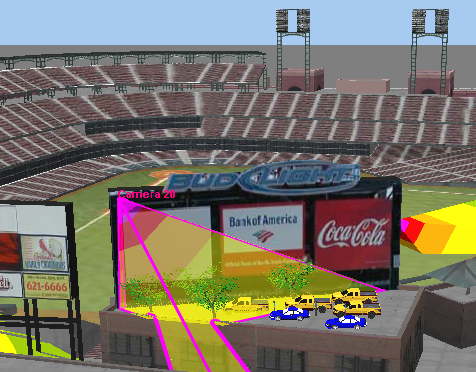
3D visualization of the active camera coverage on the environment taking into account pixel density, shadows, lens distortion.
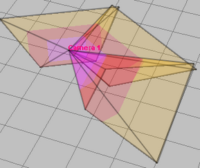
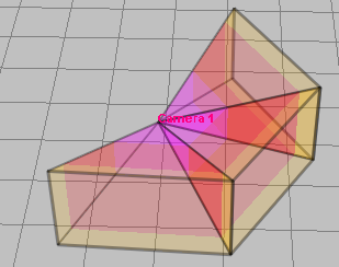
3D visualization of control areas on 360 degrees.
Free cutting 3D layout by six planes to provide access to any point of complex 3D buildings.
Working with multilevel 3D layouts and terrains with complicated vertical structure.
Possibility of loading prepared 3D models. More than 150 3D models in the library.
You can import 3D models from files *.3ds, *.ase (3D Studio max), *.dae, *.xml (Collada), *.obj and more than twenty 3D formats. You can use Collada 3D models from the free 3D Warehouse library, designer's libraries for 3DS Max, game model libraries, you can create models in SketchUP, save them in *.dae and import in VideoCAD.
You can cut out parts from 3D models, import parts from complex 3D models.
You can delete parts from 3D models.
You can import 3D models and scenes from SketchUp using free VideoCAD Plugin for SketchUP 2.0. The package includes a plug-in, an example and a User Guide with step-by-step instructions on how to add a new 3D model to VideoCAD library.
You can create 3D models in VideoCAD itself from selected constructions and existing 3D models in any combinations, ability to merge 3D models and constructions.
Possibility of using 3D models-territories, to place inside them cameras, constructions and other 3D models.
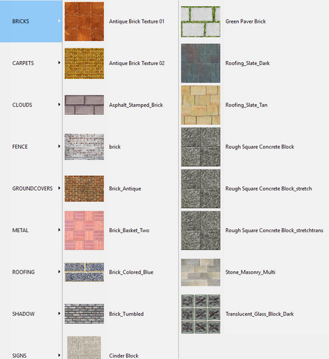
All constructions can be not only painted, but also covered by materials. Any raster images in the formats *.bmp, *.jpg, *.gif, *.tif, *.png can be used as materials. Using materials you can significantly improve appearance of images of the project.
|
Modeling observed scene parameters (illumination, visibility limitations).
Model luminaires considering spectrum of radiation and spectral sensitivity of image sensors, including discharge lamps with complex spectrum and infrared LED illuminators.
Model camera parameters (spectral response, number of pixels, resolution, minimum illumination at known signal/noise ratio, IRE and aperture, maximum signal/noise ratio, electronic shutter, AGC, BLC, gamma, day/night cameras,frame rate, interlace scan, global shutter and rolling shutter).
Model lens parameters (focal length, aperture, auto iris DC and Video Drive, resolution).
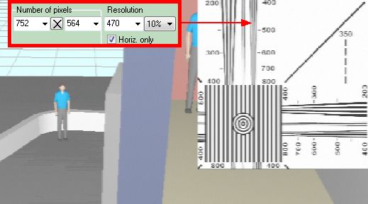
Visually control modeled resolution with the help of the Test chart
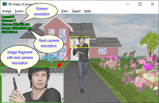
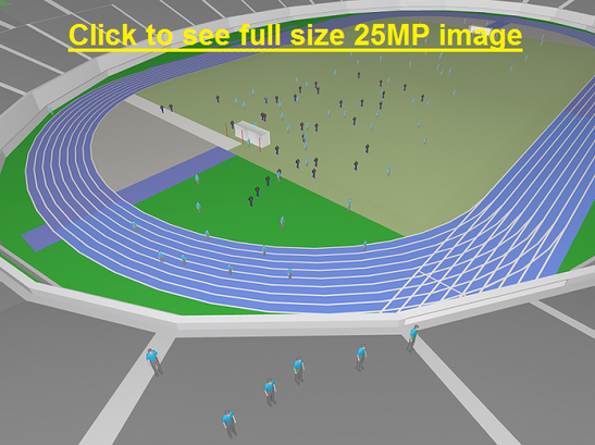
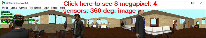
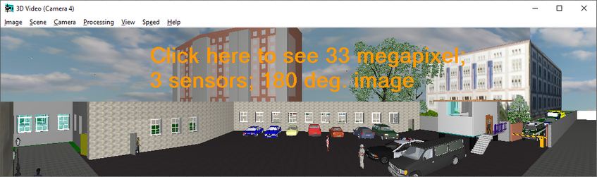
Model images from megapixel cameras with number of pixels exceeds Windows screen number of pixels (Up to 100 megapixel and more!) with PiP (Picture in Picture) and without PiP.
See examples: 5 megapixels,10 megapixels, 25 megapixels.
Calculate and model depth of field of each camera in project.
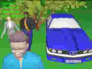
Model brightness, contrast, compression, horizontal and vertical sharpness.
Model moving objects, camera frame rate, create animated images with moving 3D models.
Model blur and distortion of moving 3D models depending on camera parameters (exposure time, interlacing, rolling shutter).
Modeling images taking into account lens distortion (barrel and pincushion). Correct modeling wide-angle lenses with strong distortion.
Obtain Image Model for each camera in the project based on models of scene and equipment. |
Simulation of Day/Night cameras. Setting the camera sensitivity in color and black-and-white modes. Setting the moment of switch to the black-and-white mode.
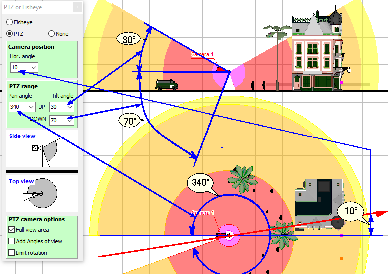
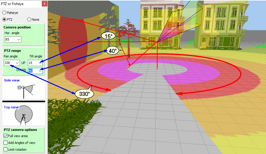
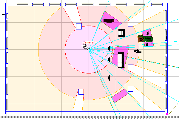
Modeling horizontal and vertical projections of the view area and visualization of the pixel density of PTZ cameras.
Visualization in 3D of the coverage area on the surrounding objects and the pixel density distribution of PTZ cameras.
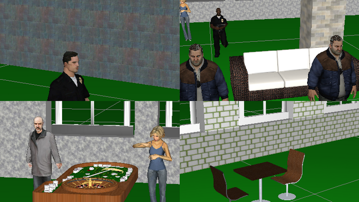
Modeling presets of PTZ cameras.
Images from presets of PTZ cameras.
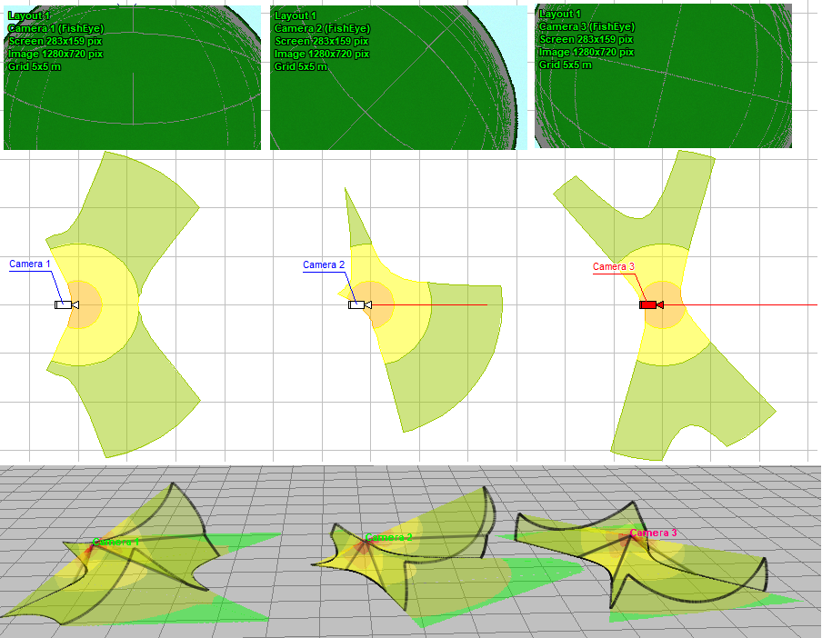
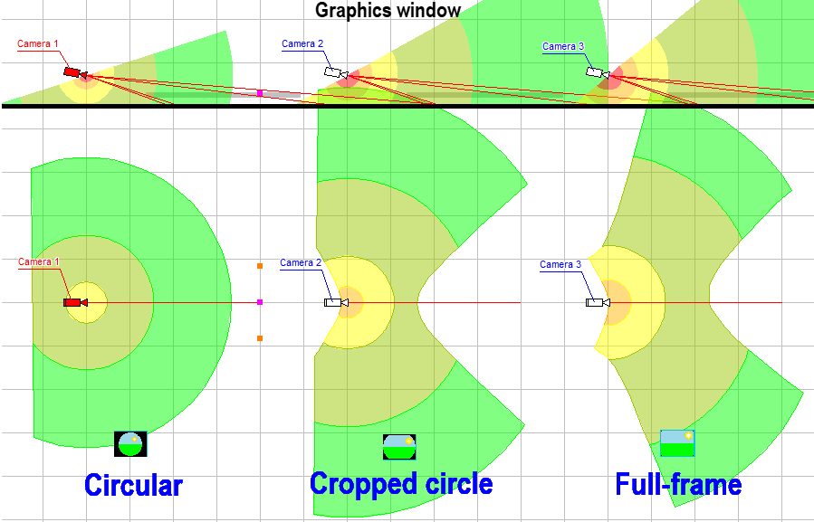
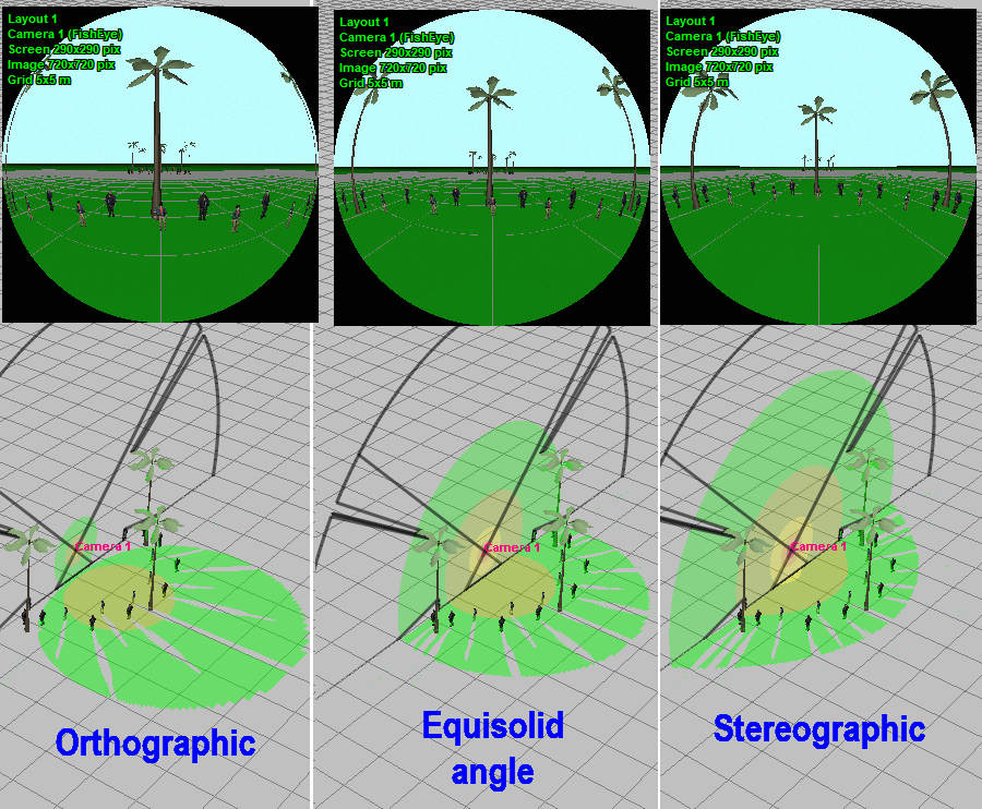
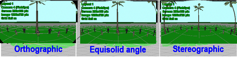
Modeling horizontal projection of view area and visualization of distribution of the pixel density of cameras with Fisheye lens.
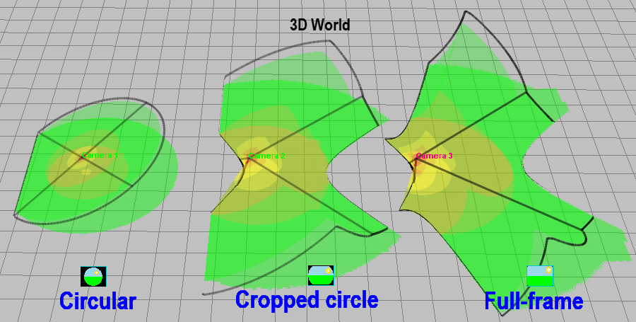
Visualization of the coverage area on the surrounding objects and the pixel density distribution of cameras with Fisheye lens.
Modeling round images from Fisheye cameras with real resolution.
Modeling combined round images from Fisheye cameras with one fragment with camera resolution.
Modeling dewarped image fragments from Fisheye cameras with camera resolution.
Modeling Fisheye cameras with view area cropped by the image sensor (Cropped circle and Full frame), as well as any intermediate variants of the Fisheye view area.
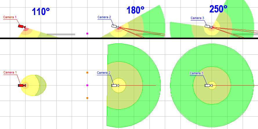
The ability to change the maximum (circular) view angle of Fisheye lenses in the range of 110-250 degrees. Thus, it is possible to simulate both narrow-angle and ultra-wide-angle Fisheye cameras.
Possibility of modeling the Mapping function of Fisheye lenses. The Mapping function determines the distribution of the pixel density between the center and edges of the field of view and depends on the internal structure of the lens.
The ability to independently set the circular angle of view of the lens, cropping of the field of view on the size of the image sensor, the aspect ratio, and the Fisheye mapping function allows you to simulate a variety of wide-angle cameras with angles up to 250 degrees using the Fisheye parametric model.
Modeling horizontal projection of view area and visualization of distribution of the pixel density of multisensor cameras with arbitrarily directed modules.
Visualization of 3D view areas of multisensor cameras.
Modeling images from multisensor cameras with arbitrarily directed modules.
Modeling multisensor cameras with horizontal directed modules.
Modeling multisensor cameras with linked modules and arbitrary position in space (tilt angle, rotation angle around its axis).
Modeling matrix multisensor cameras with linked modules directed in two dimensions and arbitrary position in space.
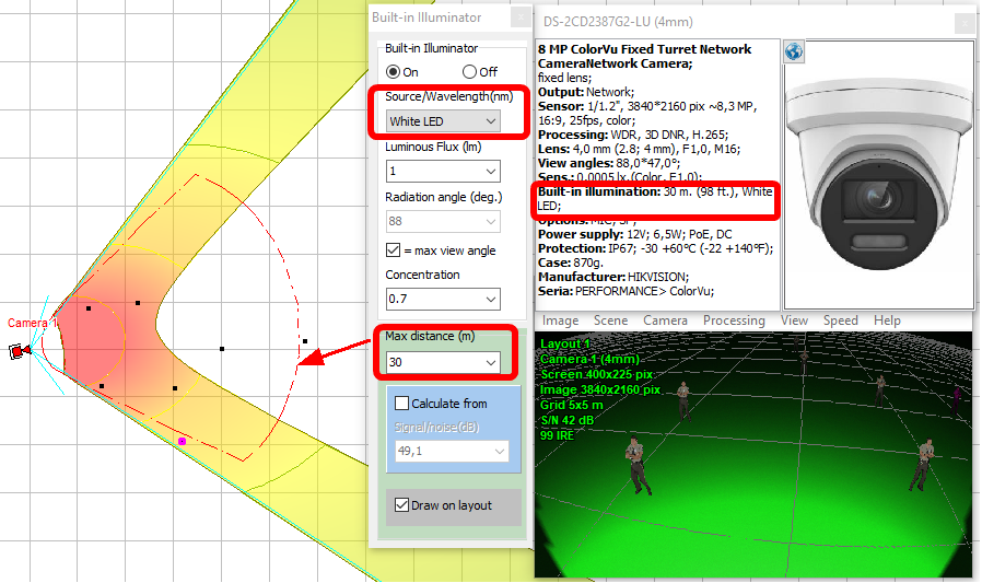
Calculation and draw on layout the IR illumination zone (where the built-in IR illumination provides an image of the target with a quality not worse than the specified one) The calculation is carried out based on the camera parameters (sensitivity, lens aperture), IR illuminator parameters (wavelength, power, radiation angle, concentration) and the required target image quality (signal-to-noise ratio).
Instead of a rigorous calculation, you can draw a projection of the IR illumination zone, setting only the maximum distance of the IR illumination and the angle of radiation.
3D modeling of built-in IR illumination based on camera and illuminator parameters.
Simulation of cameras with built-in visible light illumination and mixed illumination (IR + visible light).
|
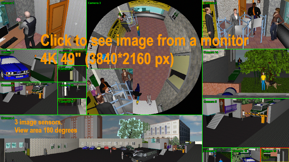
Design operator interface using the Monitor window.
Modeling size and resolution of monitors.
Create animated monitor models as html files with moving 3D models and different frame rates of each camera. See an example of animated monitor (file size about 4 Mb). |
Bandwidth and storage space calculator – is a tool for calculating network bandwidth needed for IP cameras (video encoders) and disk space required for storing video archives. It is a well-proven IP Camera CCTV Calculator integrated into VideoCAD as a tool.
With the Calculator you can:
Calculation can be carried out for IP cameras that generate up to 3 simultaneous video streams (Viewing, Recording, Alarm recording) with different resolution, compression, frame rate and recording time.
Calculation can be carried out for a single IP camera, all cameras in the project, as well as for isolated groups of IP cameras, that is useful to estimate the load of separate network segments or equipment. Filtering and sorting are possible in the Table. It is possible to group cameras by models, plans, groups, scenes,templates or by any combination of parameters with calculation of traffic values for each camera group.
It is possible to correct intermediate results of calculations (frame size, traffic) if you know more accurate experimental data.
The Calculator can be a simple calculator for simplified calculation only one stream from IP cameras, and a complex calculator, which takes into account three independent streams, color, sound, scene features, compression algorithm and hardware in use. The Calculator can work with different sets of input data, depending on their availability and required accuracy. Default values will be assigned to unused fields. Unused columns in the table can be hidden and excluded from the calculation. Created Table Views can be saved and restored when needed.
Source list of IP cameras can be entered manually or imported from VideoCAD working project, from VideoCAD project file or copied from MS Excel table.
Table of results or its fragments can be printed or exported to the formats: *. txt, *. csv, *. htm, *. rtf, *. xls, *. xlsl, *. xml.
It is possible to include the table of calculation results in the PDF report.
Using calculation patterns, you can customize the calculator taking into account any compression algorithms, processor features of any camera model, various scenes and your practical experience.
|
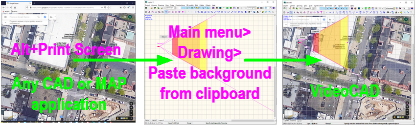
Locate cameras and cables on the prepared layouts in *.bmp, *.jpg, *.emf, *.wmf, *.png, *.gif, *.tif, *.pdf. AutoCAD *.dxf *.dwg formats. As a background, you can paste raster files from the Windows clipboard, for example, a copy of the Windows screen with a Google, OSM, Yandex map. In VideoCAD, you can crop
For backgrounds in AutoCAD *.dxf *.dwg formats you can choose Layout in the background, control visibility of layers, hide texts. For backgrounds in PDF format you can choose page and resolution of the background, cut a part from the imported file. High-quality import of vector PDF files of drawings without loss of resolution.
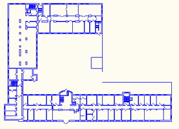
Import constructions from a 2D background in AutoCAD formats to 3D VideoCAD constructions automatically. Use of this tool allows to reduce efforts of outlining background to convert it to 3D constructions.
Import 3D models of objects and 3D models of territory from files *.3ds, *.ase (3D Studio max), *.dae, *.xml (Collada), *.obj and more than twenty 3D formats or import from SketchUP using using the VideoCAD Plugin for SketchUP 2.0.
Import raster images to display them in 3D.
Import camera model parameters to the Table of camera models via copying and pasting from Excel. |
Export the 2D drawing into any of the following formats:*.bmp, *.jpg, *.emf, *.wmf, *.png, *.gif, *.tif, *.pdf (raster and vector), AutoCAD *.dxf, AutoCAD *.dwg, PLT (HPGL/2), CGM (Computer Graphic Metafile), SWF (Adobe Flash).
Advanced export to AutoCAD formats. At exporting to AutoCAD DWG and DXF formats, cameras and illuminators are exported as blocks. The most important parameters of cameras and illuminators are recorded to the block attributes. VideoCAD layers, fonts and line types are exported.
When you export a drawing with a background in AutoCAD DWG/DXF format, VideoCAD constructions can be added to the background on separate layers or the background can be added as an external links to the file of the background. In both cases the structure of the background is saved.
Possible scheme of the combining AutoCAD + VideoCAD: 1. Load drawing in AutoCAD format as a background; 2. Import AutoCAD lines to VideoCAD 3D constructions automatically; 3. Adding cameras and constructions on special layers. 4. Export the obtained drawing to AutoCAD format to work with it in AutoCAD.
Export of the 3D scene with cameras and objects to an open COLLADA file (* .dae). COLLADA files can be imported by many 3D editors including SketchUP. VideoCAD can also import COLLADA files. See more about COLLADA file https://en.wikipedia.org/wiki/COLLADA
Export to DXF file 3D view areas and camera coverage taking into account lens distortion, pixel density, and shading.
This feature allows the convenient scheme of work with combination of 3D BIM Software (SketchUP) + VideoCAD. 1. Export layout as a 3D model-territory through SketchUP and loading it into VideoCAD. 2. Adding cameras with 3D view areas in VideoCAD. 3. Export 3D view areas in COLLADA or DXF format, loading them into 3D BIM Software and combining with the original layout in 3D.
Export images from the 3D World window to any of the following formats: *.bmp, *.jpg,*.gif,*.tif,*.png. Size in pixels of the exported file can exceed the Windows screen size.
Export 3D images from cameras to any of the following formats: *.bmp, *.jpg,*.gif,*.tif,*.png. Size in pixels of the exported file can exceed the Windows screen size.
Export animated image models with moving 3D models to animated gif. See an example of animated monitor (file size about 4 Mb).
Export images from monitors to *.bmp, *.jpg,*.gif,*.tif,*.png.
Export images from monitors to animated monitor models as html files, with moving 3D models, taking into account frame rate of each camera.
Obtain the text report with full description of all cameras in the project, view areas and cables to be pasted into a project explanatory note or used as instruction for installation.
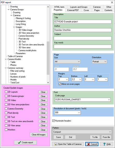
Get a report in PDF format, with full description of all cameras in the project, view areas and cables. The PDF Report can include images from the cameras, fragments of layouts with camera placed, a cover with logo. Report parameters and the structure of information in the report is configurable.
See examples of VideoCAD reports:
To see the Real camera resolution, zoom-in images in Acrobat Reader. Especial interesting are Camera 3 and Camera 4.
Obtain the cable report.
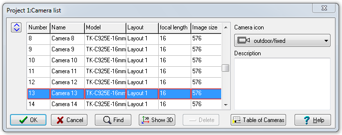
Copy the Camera list with most important parameters to MS Excel, MS Word and other software.
Get detailed adjustable table of all initial and calculated parameters of cameras in project. Print the table or export it to *.txt, *.csv,*.rtf, *.xls, *.htm formats.
|
Printing the obtained 2D drawing in raster or vector mode on one or several pages for pasting together. You can use prepared frames with standard title-block and logo. Sizes, colors styles of fonts and lines, weights of lines can be adjusted.
Printing image models from cameras and monitors.
Printing 3D images from the 3D World window.
Printing the Table of cameras and the Table of camera models as a whole or by selected fragments. |
Maintain database of camera models, assign different models to cameras in project, compare models with each other.
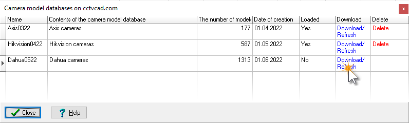
VideoCAD distribution kit includes a database of modern cameras from well-known manufacturers. VideoCAD can model all modern types of camera models in accordance with their specifications.
It is possible to download new databases of camera models from the site cctvcad.com.
You can add any camera models to the database yourself.
You can order special Camera model database add-on file, including parameters of user-defined models, entered according to their specifications.
|
Starting from version 11.1, licenses of all modifications of VideoCAD are supplied with a registration code. USB dongle is not required.
A personal license allows you to simultaneously install the program on two computers (work and home or mobile) belonging to the license owner. The username on both computers must be the same.
A corporate license allows simultaneous installation and launch on the number of computers specified in the license at ordering.
With a personal or corporate license, you can freely reinstall the program on new computers. To reinstall the program on a new computer, just uninstall the program from the old computer and install it on the new computer. The number of reinstallations is not limited.
Licenses with USB dongle are supported too. A license with USB dongle does not limit the number of computers on which the program can be installed simultaneously, but the program can only be run on a computer with connected USB dongle. The program with dongle does not use the Internet. Changing a license without dongle to a license with dongle and vice versa is possible by request of the user.
Licenses of VideoCAD allows free use of the demo versions for educational purposes, for research, theses, writing articles, etc. non-profit activities.
|
In case of a license without USB dongle, VideoCAD can transfer to the developer's site only information necessary for the operation of the licensing system in form of hashes. A hash is a digital fingerprint. Using hashes, it is impossible to restore the original information about the computer and the user. VideoCAD does not transmit any other information. In case of a license with USB dongle, VideoCAD does not transfer anything.
Thus, with any type of license, you can be sure that your personal data, information from your projects about the equipment used is not transferred outside your computer.
|
VideoCAD will help you: spare the means and win tenders due to optimization of cameras' quantity in projects and increase of their efficiency, reduce time expended and boost design quality, cut down the amount of controversial situations with customers and accelerate their solution.
VideoCAD can be used for the prompt, but exact calculations of view area projections to draw on a location plan when performing a graphical part of CCTV project. It can be also used to perform scrupulous analysis complicated cases to choose the most suitable camera location and lens parameters.
VideoCAD is employed by security firms, army, police, universities and security department of many companies worldwide.
VideoCAD is effective for CCTV designer training.