|

|

|

|

|
|||
|
Menu items |
|
|
|

|

|

|
|
|
|
|
|
|
|||
|
Menu items |
|
|
|
|
|
|
|
|
||

See Main menu location.
Menu items substantially duplicate the buttons of the tool bar; however, there are certain advanced tools.
Keyboard shortcuts. can be assigned to each menu item.
Create new project. A project may contain unlimited number of cameras and up to 10 layouts.
In the New project dialog box type the new project name.
You can change the format of measurements in new project when necessary: Metric (meters, millimetres) or Imperial (feet, inches).
|
Open earlier saved project. Choose a project file. If the current project was not saved, VideoCAD offers to save it.
|
Save project to a file. If a project is saved for the first time, the dialog box Save as appears enabling to change a project filename and a saving directory when needed.
|
Save project to a file under another name or in another directory. In the appearing dialog box choose a filename and a directory to save it.
The project includes all information on the program settings (line types, fonts, etc.). Thus, the saved project can be used as a template for new projects.
|
Project > Import from VideoCAD3..6
Import of the previous project format *.vmp, supported by VideoCAD versions from 3 to 6.. In the appearing dialog box choose a filename with *.vmp extension.
If after importing project seems incorrectly, - restart VideoCAD.
|
Project > Export to VideoCAD3..6
Export current project to the previous project format *.vmp, supported by VideoCAD versions from 3 to 6.. In the appearing dialog box choose a filename with *.vmp extension.
*.vmp file can contain no more than 100 cameras and no more than 5000 constructions on each layout. All that exceeds these limits, will be lost. Also new tools which appeared in VideoCAD7-9 will not be saved.
|
Export the data on most of the specified and calculated parameters of cameras and cables included into the current project to a text file.
Enter a filename. A default filename coincides with the project name.
When clicking OK, the text document obtained is automatically loaded into a text editor for viewing and editing.
You can copy and paste the text obtained into a project explanatory note.
All parameters of cameras in the project can be obtained in the form of adjustable table which can be exported into various formats. You can get a report in PDF format.
See also: PDF report , Table of cameras, Cable report
|
Export the data of the specified and calculated parameters of cameras and cables included into the current project to a PDF file.
The PDF report may include the Cover with arbitrarily placed texts and pictures, Table of contents, Tables with camera parameters, Table with camera model parameters and Table of cables, images from cameras, fragments of layouts with placed cameras, 3D views of camera view areas from the 3D World window, Images of pixel density patterns, Photos of camera models, summary information on cameras, footers and headers with texts and pictures, arbitrary texts (introduction, conclusion), external PDF files attached to the report, background PDF file, pages of which are drawn as a background for the Cover and report pages.
Design of the report and composition of information in the report are customizable.
The PDF report is integrated with the Table of Cameras and the Table of Camera Models. Flexible filters of the tables are used to filter and sort cameras for inclusion in the report by simple or complex conditions. Views of the tables are used to select and order camera parameters in the tables of the report.
You can save report settings to patterns, select saved pattern from the list, save report patterns to a file, and load from files.
After choosing this menu item, a box for configuring the PDF report parameters will appear.
See more details about PDF report: PDF Report
See also: Text report, Table of cameras, Cable report
|
Project > Keep window positions
Keep positions of the program windows when VideoCAD is running on multiple monitors and between program launches.
|
Project > Default window positions
Additional VideoCAD windows can be positioned and scaled for your convenience. Changes to the position of windows will be remembered if the Keep window positions option is checked. By clicking on the default window positions item, you can return the default positions and sizes for all additional windows.
|
Exit the program.
|
Create new camera with default parameters.
Later it is possible to change name, number, icon of the camera and the additional information in the Camera list box. Cameras can be numerated sequentially with the help of the Numerate cameras tool. Cameras are displayed by different icons only if the Display camera type box in the Options box is marked.
On the Line type panel it is possible to choose line type by which the icon of the camera and View area projection bounds will be drawn. When displaying pixel density is disabled, projection will be filled (hatched) by the color of assigned line type. Later it is possible to change line type using Change line type tool. Hatch style is determined by style of a line type, assigned to the camera (solid, dash, dot, dash dot etc.).
After entering all necessary data click OK, to cancel the operation click Cancel.
If there is already a camera with chosen number in the current project, VideoCAD will ask to specify, whether you would like to rewrite it. After camera creation specify by clicking a place for the new camera on the layout. Just after camera creation the moving mode will be switched on. When placing will be completed, click
It is convenient to create new cameras with already set parameters by copying and pasting existing ones.
At the moment of placing new camera or pasting copied camera, its base height is set to the base height of the active layer.
|
All the specified and calculated parameters of the active camera and layout are saved to the current project.
Saving is performed automatically at many operations.
|
Clicking this button opens Camera list box, in which camera list of current project is displayed. Active camera is highlighted by red frame. Any camera can be activated, removed, renamed, found on layouts, it is possible to show 3D image from any camera. It is also possible to sort cameras in the list. For carrying out any manipulations with the camera first select its name in the list by single clicking.
See more: Camera list
|
Show interactive Table of parameters of all cameras in the project. The table can be exported to *.txt, *.csv, *.htm, *.rtf, *.xls formats.
See more: Table of cameras
|
Open the Numerate cameras tool. This tool allows renaming and serial numeration any quantity of cameras simultaneously.
See more: Numerate cameras
|
Show the PTZ or Fisheye panel. On the panel there are tools for modeling PTZ cameras and cameras with Fisheye lens.
For details see: PTZ or Fisheye.
|
Show the Built-in illuminator panel. The panel contains tools for modeling the built-in infrared illumination of cameras (infrared
See more: Built-in illuminator, Modeling Built-in IR illuminator
|
The item allows you to quickly switch the camera to corridor mode and back. In corridor mode, the camera rotates 90 degrees around the optical axis, the horizontal and vertical of the field-of-view are swapped.
The item is unavailable if the camera is assigned a model with no corridor mode. If a model is assigned to the active camera, for which the corridor mode can work at a resolution not exceeding a certain one, then if the camera's resolution exceeds the certain value, a warning is displayed.
When calculating pixel density, the influence of the corridor mode on the position of the vertical and horizontal in the frame is determined using the When rotating camera around its axis or in corridor mode, bind horizontal/ vertical combobox in the Options box.
The item is duplicated in the Camera geometry box and on the Toolbar.
|
Show the Camera groups panel. Cameras on the same layout can be combined into groups. On each layout there can be an unlimited number of groups. Group management is carried out using the Camera groups panel.
For details, see the Camera groups panel.
|
Camera > Add camera to active group
Add active camera to active Group of cameras. If there are selected cameras other than the active one, then the
See more. Camera groups
|
Camera > Activate next camera in the group
Clicks on this button sequentially activate cameras from the group in which the active camera is located. You can also select the camera from the drop-down menu. The button is useful if all cameras of a group are at the same point, which makes it difficult to activate an individual camera.
For details, see the Camera groups panel.
|
Camera > Positions of active camera / Multisensor
Positions are copies of cameras that can be copied from and into the active camera.
Positions can be displayed simultaneously with the parent camera in the Graphics window and the 3D World window. Pictures from positions can be displayed simultaneously in the 3D Video window, loaded to monitors, included in the PDF report.
The button opens a window with tools for managing positions of the active camera. The window has a tab for modeling multisensor cameras based on positions.
For details see: Positions of active camera / Multisensor.
|
Camera > Table of camera models
Show Table of camera models. In the table it is possible to set parameters to models and assign any model to the active camera. The table can be exported to *.txt, *.csv, *.htm, *.rtf, *.xls formats.
See more: Table of camera models
|
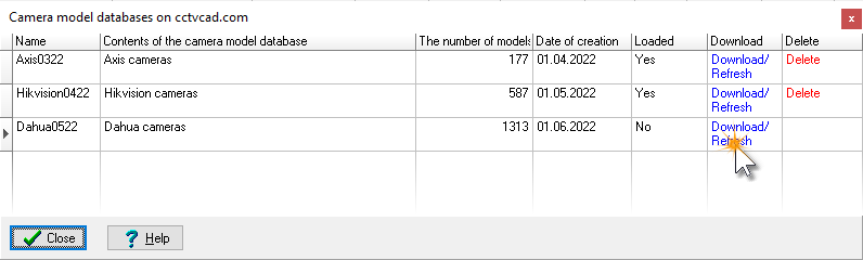
Camera > Camera model databases on cctvcad.com
Calling a window with a Table of databases of camera models located on the site cctvcad.com. You can copy these databases to your local database of camera models available on the All models tab of the Table of Camera models.
To add camera models from the selected database to the local database of camera models, click Download/Refresh. To remove models belonging to a certain database from the local database of camera models, click Delete.
To add only certain models from the selected database:
1. Add the entire database (Download/Refresh). 2. In the Table of Camera Models, duplicate the models you need. 3. Delete the entire database (click Delete).
This item is duplicated as the
See also: Database of real camera models, Adding a camera model to the Camera model database
You can order special Camera model database add-on file, including parameters of user-defined models, entered according to their specifications.
|
Open the Camera model card window. If the window is called by the button on the Graphic window toolbar or the menu item, a photo of model of the active camera is dynamically displayed in the window.
For detail see: Camera mode card
|
Clicking this button make visible the active camera with it's view area in the graphics area. The scale is chosen automatically. If the Active camera is disposed in another layout, the correct layout is activated.
In this mode the scale changing and drawing dragging are not available. It is convenient to use this tool at both projections switched on, and also together with the Edit active camera tool. For switching off this mode, click the same button once again.
|
Clicking this button switches the Active camera into the graphical editing state.
A drawing in the graphics area rotates so that the direction of the main optical axis of camera lens becomes parallel to the display plane, and view area edges of the active camera are displayed in lines of double thickness. The view area upper and lower bounds are displayed in horizontal green lines.
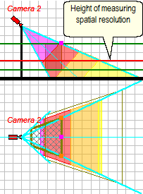
If the Pixel density is displayed, the horizontal red line indicates the height of measurement of the pixel density.
This state enables the detailed analysis of view area using the test object. In the vertical projection calculation of the depth of field, the calculating the field-of-view sizes at any point of view area and displaying Pixel density. Test object can be seen in the 3D Video in the graphical editing state.
In the graphical editing state of the active camera, selection and rotation of the active camera is blocked to prevent displacement of the background, constructions and cameras relative to each other on other layouts.
See more: Graphical editing state.
|
Camera > Change installation height
When this button is pressed clicking in a vertical projection specifies a new height of the Active camera installation. The values of camera installation height in the Camera Geometry box change according to a clicked point height.
|
Camera > Change view area upper bound
When this button is pressed clicking in a vertical projection specifies a new height of the view area upper bound and new distance up to the view area upper bound. Clicking in a horizontal projection specifies a distance up to the view area upper bound. The values of correspondent parameters in the Camera Geometry box change to clicked point coordinates.
You can change view area upper bound in Select / Edit mode, by moving the the grip in the middle of the view area upper bound.
|
Camera > Change view area lower bound
When this button is pressed clicking in a vertical projection specifies a new height of the view area lower bound. The values of view area lower bound height in the Camera Geometry box change according to a clicked point height.
|
When this item chosen clicking in the graphics area specifies a new position of the active camera relative to the view area upper bound, test object, constructions and other cameras. All the parameters' values are recalculated.
|
Camera > Move active camera name
When this item chosen, clicking in the graphics area specifies new location of the active camera name relatively to its icon in the projection which you clicked.
If the Options box>Camera and Illuminator>Camera Icon>Scalable is not checked, then the size of the camera icon is not scalable so the distance up to the name also cannot be scalable. The distance is saved in pixels. If the Scalable is checked, then the size of the camera icon is scalable so the distance up to the name is scalable too. The distance is saved in meters(foot).
Scalable and unscalable positions are stored separately, so switching the Scalable box will not lead to losing of the saved positions of the camera name.
|
Camera > Extension line for camera name
|
The item opens a submenu in which a format of saving drawing file can be chosen. You may save the drawing in any of the following formats: *.dxf, *.dwg, *.wmf, *.emf, *.emf+, *.gif, *.tif, *.png, *.pdf (raster and vector), *.plt (HPGL/2), *.cgm (Computer Graphic Metafile), *.swf (Adobe Flash), *.bmp, *.jpg.
Export to DXF and DWG (AutoCAD) is possible only in VideoCAD Professional
To the *.png, *.pdf (raster), *.bmp, *.emf+ (vector) formats, a copy of the image in the Graphics window is exported practically without artefacts. The default export is performed with the same resolution as on the screen. You can increase the resolution of the drawing on the Export tab in the Options box. Therein you can also configure other export parameters.
Export to AutoCAD *.dxf, *.dwg is much more than a copy of the image in the Graphics window:
To make transparent fillings of view area projections: 1. Before exporting, mark the View areas on special layers checkbox in the Options box. 2. After opening the file in AutoCAD, change the Transparency of layers with view areas VC_ <layer name> view areas.
To prevent regions with high pixel density in the resulting AutoCAD file from obscuring by regions with low pixel density, mark the High resolution on top checkbox in the Options box before exporting.
1. Load drawing in AutoCAD format as a background; 2. Adding cameras and constructions on special layers. 3. Export the obtained drawing to AutoCAD format to work with it in AutoCAD.
See more: Work with background in AutoCAD format More about export options to AutoCAD: Options box>Export>DXF,DWG,PLT,CGM,SWF,vPDF
*. wmf format is very outdated, it does not support images of 3D models, semitransparent (blend) and gradient filling projections. *. emf format does not support gradient and blend filling.
While saving to vector *.pdf, the transparency and rotation of 3D model projections are not saved.
An alternative way to export to *.pdf is to print to a virtual printer, which produces printing result as a PDF file. In this method, the weight and color of lines, fonts will match the values specified for printing.
While saving to *.gif, color distortions are possible, while saving to *.jpg compression artefacts can be visible .
While saving to other formats, mentioned above and other distortions are possible.
Clicking a sub-item with extension name will open the Export tab in the Options box. It is possible on the tab to adjust export parameters: exporting drawing scale, camera icon and illuminator icon sizes, size of nonscalable fonts, step of dash line and step of hatches.
After closing the Options box the dialog box Save drawing as appears enabling to choose a filename and a saving directory. The file name coincides with the layout name by default.
You can save the drawing with a frame and tittle-block. To do this chose Print, chose frame with a tittle-block then save the drawing.
If export module of VideoCAD can not export drawing with a complex background in AutoCAD format, try the following:
Shift and rotation between background and drawing are possible when exporting drawing with a background in AutoCAD format with the active User Coordinate System (UCS). The shift can be corrected in AutoCAD. To prevent the shift do not use as a background files with the active User Coordinate System. Use the files in the World Coordinate System (WCS). Before loading a file with UCS as a background, open it in AutoCAD and use the PLAN command.
If the dxf or dwg file obtained as a result of export can not be opened in AutoCAD, then a likely cause of the error is use of special non-alphabetic characters in tests (names of cameras, layers, camera groups, in texts). Remove any suspicious characters and re-export.
See also: Export of 3D view areas to DXF, Work with background in AutoCAD format,Options box>Export, PDF Report
|
The menu item is intended for converting graphics files and VideoCAD constructions in the high resolution *.emf file. When converting, cameras images, titles and grid are excluded from the obtained file.
Thus, the obtained file contains:
If necessary to hide constructions, use the item Background only.
|
Copy drawing to Windows clipboard.
Choosing this item opens a submenu allowing to choose the format in which the drawing will be copied to the clipboard.
After that the drawing can be pasted into any document, e.g. into a project explanatory note. A drawing is copied in a displayed size.
|
This item opens a submenu allowing to choose a projection to load a background.
After choosing item a dialog box for choosing background file appears. Graphic files of the following formats can be used as a background: *.bmp, *.jpg, AutoCAD *.dxf, *.dwg, *.wmf, *.emf, *.emf+, *.gif, *.tif, *.png,*.pdf.
Choose the necessary file in the dialog box and click OK.
The background will appear in the chosen projection along with the dialog box Adjust background. Using its tools is necessary to bring an image scale on the background in correspondence with the general VideoCAD scale.
See further: Adjust background
If VideoCAD can not read a file in AutoCAD format or reads it incorrectly, proceed as follows:
VideoCAD is not capable of processing all possible AutoCAD files. Usually simple AutoCAD files are processed well, but some complex files cannot be imported or imported with an error, some files can be opened, but cannot be exported or exported with an error, or cannot be converted to 3D constructions using the Import DXF/DWG background tool. In case of any problems with the AutoCAD file, it is recommended to simplify it, but it is better to create a new file and copy only structures needed for the design into it.
See also: Adjust background, Move background, Hide background,Delete background, Thin lines of raster background.
|
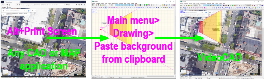
Drawing > Paste background from Clipboard
Paste raster background from Windows clipboard.
The tool allows you to quickly turn a screen image from any graphics program, Google, OSM, Yandex maps into a background:
1. Expand the program window with the terrain map on the screen. To display a full screen map from the Internet browser, press F11 on the keyboard. 2. Press Print Screen (or Alt + Print Screen) on the keyboard. 3. Open VideoCAD and select Menu> Drawing>Paste background from clipboard. 4. Click Crop background
This handy method of importing maps is suitable for any program, allows to get background of several monitors size and does not depend on third-party services.
|
This item opens a submenu allowing to choose a projection to adjust background.
After choosing item the dialog box Adjust Background appears. Using its tools is necessary to bring an image scale on the background in correspondence with the general VideoCAD scale .
Sequence of actions:
|
This item opens a submenu allowing to choose a projection to move background.
After choosing this item by 2 clicks in the graphics area specify start and end points of moving the background in the corresponding projection.
|
This item opens a submenu allowing to choose a projection to hide background.
The hidden background and all its parameters are stored in memory, but the background is not displayed. It is convenient for increasing speed on weak computer or in some other cases.
If export module of VideoCAD can not export drawing with a complex background in AutoCAD format, try the following:
|
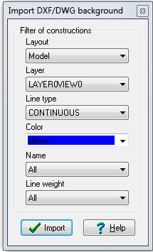
Drawing > Import DXF/DWG background
Using this tool you can import 2D constructions from a background in AutoCAD formats to VideoCAD 3D constructions automatically. Use of this tool allows to reduce efforts of outlining background to convert it to 3D constructions. Specially prepared background file is not required, but if a background is pre-prepared in AutoCAD, then the efficiency of import will be higher.
Imported constructions are usual VideoCAD constructions, you can edit them. You can repeat steps 3..7 many times, to import different constructions from the background to different construction types of VideoCAD, on different heights, to different layers, by different colors etc. Not all types of background constructions can be imported. Starting from VideoCAD8 you can import lines and polylines on the layout or in blocks.
The Import DXF DWG background tool turns AutoCAD lines into VideoCAD 2D/3D constructions. If there are a lot of lines in the AutoCAD file then we get a lot of confused constructions, which can overload the computer. For a good result, it is recommended to use the Import DXF DWG background tool only with simple AutoCAD files, with low number of lines, and also use the line filters of this tool. The best result of the tool can be obtained with special prepared AutoCAD files where each line corresponds to a vertical plane. If this tool does not give a good result with your AutoCAD background, please create 3D environment by manually tracing lines on the background using constructions, as in the case of background in other formats, or create a specially prepared AutoCAD file based on your background.
See also: Work with background in AutoCAD format
|
This item opens a submenu allowing to choose a projection to remove background.
Choosing item from the submenu removes background and all its parameters from the project.
If the background is already loaded, and you load a background without removing the previous one, then the size, scale and location of a new background will remain the same as of a previous one. In this case, the proportion between the sides of a new background might be distorted. If you remove an old background beforehand, then the new one will be automatically placed according to the size of a file and the current scale on the screen.
|
After choosing this item the background only will be displayed in the graphics area.
VideoCAD turns to a handy program for graphic files viewing and printing. For all the rest to be displayed choose this item again.
|
Choosing this item opens a box with the list of current project layouts. The project may contain up to 10 layouts. Originally one layout is created into project.
See more. Layout box
To switch between layouts, create, delete, rename layouts in the Graphics window it is convenient to use the Layouts tabs in the lower left corner and the pop-up menu of these tabs.
|
Show the Layers panel. Cameras and constructions can be distributed by layers. On each Layout unlimited number of layers can be. Control of layers is performed by the Layers panel.
See more: Layers panel
|
Choosing this item opens a standard dialog box of current printer setup in Windows.
|
After choosing this item the borders of pages for printing and the Preview box appear in the graphics area.
|
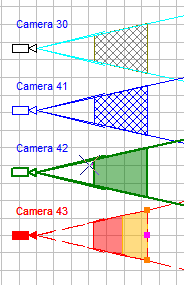
Assign a color for the active camera and its view area in the Graphics window and in the 3D World window.
The fill of the view area projections will be colored only if the pixel density visualization of this camera is disabled.
The color is assigned regardless of the line type of the camera.
White color means no color assigned. In the case of the assigned white color (no color assigned), if the line type of the camera equal the default line type for camera icons specified in the Options box, the colors of elements for such a camera are taken from the Options box> Lines> System Lines. By default, cameras are assigned line type number 21. If a different line type is assigned to the camera, the colors of elements for that camera are taken from the assigned line type.
Position of the button at the moment of saving the camera determines how the camera will be painted when it is not active.
If there are selected cameras on the layout, except for the active camera, then a magenta frame
|
Show the Active camera view area edges, calculated according to parameters in the Camera Geometry box.
Line type can be changed in the options box.
A button state at the moment of camera saving determines whether the view area edges of the given camera will be displayed when this camera is inactive.
If selected cameras exist on the current layout, except the active camera, this button changes view
|
View > View area projection bounds
Show the bounds of the Active camera view area projections or sections of the view area on two levels calculated according to parameters in the Camera Geometry box.
Submenu of the button:
Difference between the View area projection bounds and Shadows buttons is that the View area projection bounds are built without obstacles on the scene but the Shadows are built considering obstacles. Both buttons can be used simultaneously in various combinations.
3. Off. - don't show.
When View area projection bounds is disabled, but Shadows is enabled, the View area edges is shown simplified in the form of two rays if the angle of camera rotation around its axis is multiple of 90 degrees or in the form of one ray if the angle of camera rotation around its axis is not multiple of 90 degrees.
If the line type of camera coincides with default line type for camera icons, specified in the Options box, then for this camera the line type of View area projection bounds is taken from the Options box>Lines>System line types>Bounds. This line type is assigned to new cameras by default.
If another line type was assigned to the camera, the View area projection bounds of this camera is drawn by this line type assigned to the camera, as well as the View area edges and camera icon.
See also: Camera color
A button state at the moment of camera saving determines whether the bounds of the given camera view area projections will be displayed when this camera is inactive.
If selected cameras exist on the current layout, except the active camera, this button changes view
|
Hatch or fill by blend color view area projections of active camera ( if these projections exist) calculated according to parameters in the Camera Geometry box.
Drop-down menu:
1.
2.
3. Off - don't hatch and fill view area projections.
A button state at the moment of camera saving determines whether the filling or hatching of the view area projections of the camera will be displayed when this camera is inactive.
If selected cameras exist on the layout, except the active camera, this button changes view
|
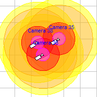
Fill in different colors regions on the view area projections of the active camera, depending on the pixel density at far bounds of these regions. Colors of the regions and the boundary values of the pixel density are determined by the pixel density pattern assigned to the camera. In the Pixel density box you can edit the patterns and assign them to cameras.
Drop-down menu: 1.
2.
In case of gradient color is chosen, the colors at the far region bounds equal to the colors of the pixel density pattern, but between the bounds color changes smoothly, as well as real pixel density. Gradient reflects the pixel density more accurately and looks impressive, but discrete colors are more intuitive and easy to use..
Calculation of gradient demands a lot of resources and increases redraw time.
3. Off. - don't display pixel density
In the Dome mode the Pixel density is calculated without taking into account pan and tilt angles of camera. It is assumed that the camera can pan and tilt freely, and pixel density is calculated at the center of the field of view.
A button state at the moment of camera saving determines whether the pixel density of the camera will be displayed when this camera is inactive.
If selected cameras exist on the layout, except the Active camera, this button changes view
See also: Pixel density box, Visualization of the camera control area projections and pixel density within them.
|
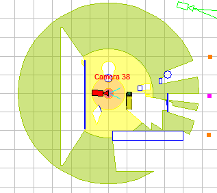
Shadows - a powerful yet easy-to-use tool of VideoCAD. Shadows are calculated for all positions of cameras, shading objects can be located at any point of space. You should only enable calculation of shadows with the help of this button.
Shading takes into account the camera installation height and all 3 coordinate of constructions and 3D models (including heights).
4. Off - disable shadow calculation and displaying.
Difference between the Shadows and View area projection bounds buttons is that the View area projection bounds are built without obstacles on the scene but the Shadows are built considering obstacles. Both buttons can be used simultaneously in various combinations.
The Shadow button works in conjunction with the Pixel density
The calculation of shading - resource-intensive operation. During the shadow calculation on the Shadow button red frame flashes You can change the resolution of the shadow calculation and optimization of the shadow calculation. The lower the resolution, the faster the calculation.
Automatic shadow calculation is performed only for the active camera. To recalculate shading for a particular camera - activate this camera. To recalculate shading for all selected cameras, click Main Menu>View>Recalculate shadows. To temporarily disable the automatic calculation of shading (keeping already calculated shadows visible) clear the item Main menu>View>Calculate shadows for active camera.
The calculation of shading from 3D models is disabled by default to save resources. To enable the calculation of shading from the 3D models, check the Options box> Miscellaneous> Shadow>Calculate shadows for 3D models. Additionally, for each 3D model, which must be taken into account when calculating the shading:
To force to calculate shadows from a type of 3D model you can mark Shadows checkbox on the 3D Models window while editing the type of the 3D model.
Whether or not a specific construction takes into account in the calculation of shading determines by the Shadow checkbox of the line type used for the construction. . You can ignore constructions of specified layers while calculating shadows, using the Shadows row in the table of layers.
A button state at the moment of camera saving determines whether the shadows of the camera will be displayed when this camera is inactive.
If selected cameras exist on the layout, except the Active camera, this button changes view
See also:Shadows,Main menu>View>Calculate shadows for active camera, Main Menu>View>Recalculate shadows,Line type>Shadow, Options box>Miscellaneous>Shadow, Layers>Shadow, Options box>Calculate shadows from 3D models, Current construction parameter panel>3D model>Shadows, 3D Models window>Shadows, Choosing the best place for PTZ (dome) camera, Visualization of the camera control area projections and pixel density within them,Shadow resolution, Shadow optimization
|
View > Calculate shadows for active camera
Enable/ disable calculating shadows.
Automatic calculating shadows is performed for the active camera only. To temporary disable automatic calculating shadows (with keeping already calculated shadows) clear this menu item.
This item controls shadow calculation in the Graphics window only, it doesn't affect shadows in the 3D World.
See also:Shadows,Main menu>View>Calculate shadows for active camera, Main Menu>View>Recalculate shadows,Line type>Shadow, Layers>Shadow, Options box>Miscellaneous>Shadow, Options box>Calculate shadows from 3D models, Current construction parameter panel>3D model>Shadows, 3D Models window>Shadows, Choosing the best place for PTZ (dome) camera, Visualization of the camera control area projections and pixel density within them
|
Recalculate shadows for all selected cameras
Calculating shadows is a resource-intensive operation. Automatic calculating shadows is performed for the active camera only. To recalculate shadows for all selected cameras, click this item.
See also:Shadows,Main menu>View>Calculate shadows for active camera, Main Menu>View>Recalculate shadows,Line type>Shadow, Layers>Shadow, Options box>Miscellaneous>Shadow, Options box>Calculate shadows from 3D models, Current construction parameter panel>3D model>Shadows, 3D Models window>Shadows, Choosing the best place for PTZ (dome) camera, Visualization of the camera control area projections and pixel density within them
|
Button state at the moment of camera saving determines whether the 3D view area of the given camera will be displayed when this camera is inactive.
If selected cameras exist on the current layout, except the Active camera, this button changes view
After enabling displaying 3D view areas of inactive cameras, it may be necessary to recalculate shadows of 3D view areas from all cameras in the 3D World window.
|
Button state at the moment of camera saving determines whether the Coverage of the given camera will be displayed when this camera is inactive.
If selected cameras exist on the current layout, except the Active camera, this button changes view
After enabling displaying Coverage of inactive cameras, it may be necessary to recalculate shadows of 3D view areas from all cameras in the 3D World window.
|
Show/Hide the active camera projections of person detection area, calculated according to parameters in the Camera Geometry box and the quality level criteria of the active camera.
If the projections are present, a lilac frame round the button Person detection area appears.
The projections are displayed in lilac color.
Line type can be changed in the options box.
A item state at the moment of camera saving determines whether the projections of person detection area of this camera will be displayed when this camera is inactive.
Clicking this item will open person detection area size box. Clicking once again close the box and hide the area projection displaying on the layout. If it is necessary to close only the box, and area displaying on the layout should be left, close the box by clicking Close in upper right corner. Person detection area displaying will remain and the button will remain pressed.
This tool doesn't take into account camera rotation around its main optical axis, shadows and lens distortion.
See also: Person detection area size box, Criteria editing box of person detection area, Pixel density box
|
View > Person identification area
Show/Hide the active camera projections of person identification area, calculated according to parameters in the Camera Geometry box and the quality level criteria of the active camera.
If the projections are present, a orange frame round the button Person identification area appears.
The projections are displayed in orange color.
Line type can be changed in the options box.
A item state at the moment of camera saving determines whether the projections of person identification area of this camera will be displayed when this camera is inactive.
Clicking this item opens person identification area sizes box. Clicking once again close the box and hide the area projection displaying on the layout. If it is necessary to close only the box, and area displaying on the layout should be left, close the box by clicking Close in upper right corner. Person identification area displaying will remain and the button will remain pressed.
This tool doesn't take into account camera rotation around its main optical axis, shadows and lens distortion.
See also: Person identification area size box, Criteria editing box of person identification area, Pixel density box
|
View > License plate reading area
Show/Hide the active camera projections of license plate reading area, calculated according to parameters in the Camera Geometry box and the quality level criteria of the active camera.
If the projections are present, a bright green frame round the button License plate reading out area appears. The projections are displayed in bright green color.
Line type can be changed in the options box.
A item state at the moment of camera saving determines whether the projections of license plate reading area of this camera will be displayed when this camera is inactive.
Clicking this item opens license plate reading area sizes box. Clicking once again close the box and hide the area projection displaying on the layout. If it is necessary to close only the box, and area displaying on the layout should be left, close the box by clicking Close in upper right corner. License plate reading area displaying will remain and the button will remain pressed.
This tool doesn't take into account camera rotation around its main optical axis, shadows and lens distortion.
See also: License plate reading area size box, Criteria editing box of person identification area, Pixel density box
|
Show on the top left corner: names of project and layout and the grid step on the drawing. When the active camera is in the graphical editing state, the name of the active camera quality level is shown in addition.
Font type can be changed in the Options box.
|
Switch on/off the displaying cameras' names near their icons in the Graphics window. In the 3D World window you can switch of cameras' names with the help of an appropriate checkbox..
Font type can be changed in the Options box.
|
Switching on/off displaying velocity vectors of 3D models.
See more: 3D model speed.
|
Show/Hide cables of the active camera.
|
Show/Hide the cables of all the cameras.
Only cables of the active camera can be edited.
|
View > Cameras over constructions
When this item is checked, cameras icons and view areas are displayed over constructions, i.e. the constructions do not cover the cameras. This mode is convenient at operation with complex 3D models of rooms. When the item is not checked, the constructions are displayed over cameras (by default).
See also: High resolution on top.
|
This Item controls overlay of view area projections of cameras with pixel density visualization. If it is not checked, the cameras with view areas are drawn in the order of their numbers in the Camera list. Active camera is drawn on top of all. In this case, cameras drawn above overlay previously drawn cameras.
In the Camera list you can change the order of cameras in the list, which means the draw order.
If this item is checked, then the order of drawing is more complicated:
In this case, all cameras are visible, despite the imposition of projections of different cameras and layout's areas controlled with high pixel density, are drawn on the top.
Enabled option somewhat slows down operation of the Graphics window; you can enable it if necessary.
See also for exporting to AutoCAD: High resolution on top.
See also: Cameras over constructions.
|
Clicking this item will open Camera Geometry box. This box includes geometric parameters of the camera, lens and installation parameters and camera resolution in pixels.
See more: Camera geometry box
|
As a result of clicking on this button, the Sensor and Lens panel will be shown.
On the panel you can set:
In addition to specifying lists, the tools of the panel can improve accuracy of modeling shape of the view area, take into account dependence of the size of active area of the image sensor on the selected resolution, and also take into account effect of lens distortion.
For details, see Sensor and Lens.
|
View > Sensitivity and Resolution
Show the Sensitivity and Resolution box in which there are parameters of sensitivity and resolution of the active camera.
Sensitivity parameters take part in modeling only if the 3D Video is opened and illumination modeling is switched on.
See more: Sensitivity and Resolution
|
Show or hide the Pixel density box. In this box it is possible to create and edit patterns of pixel density and field of view size visualization. In the box there are prepared pixel density patterns according to the following criteria: Home Office Scientific Development Branch, Home Office Guidelines for identification, P 78.36.008-99, Australian Standard AS4806: Closed Circuit Television, European Standard EN 50132-7, ISO/IEC 19794 Biometric data interchange formats, Johnson criteria for thermal cameras. Also in the box there are examples of images of group of people are automatically displayed for each region of pixel density.
See more. Pixel density box, Pixel density button.
|
Show or hide the 3D Video window. The 3D Video displays the image from the active camera.
See more: 3D Video
|
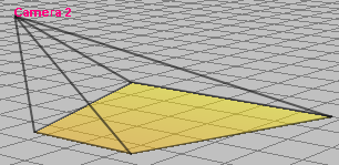
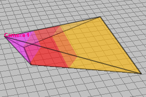
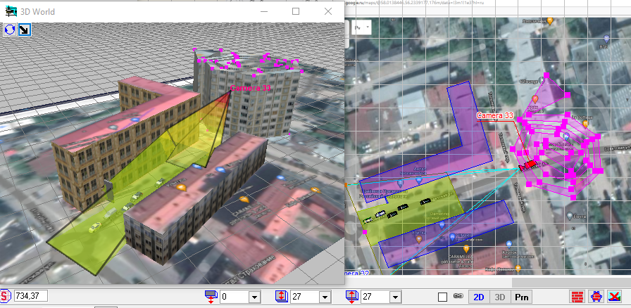
Show or hide the 3D World window. In the 3D World the project layout with cameras and view areas is shown in 3D.
See more: 3D World.
|
Show or hide the Depth of field calculation box.
If the near or the far bound of the sharpness area not intersect the horizontal plane at the height of depth of field measurement within the view area projection, then this bound is not displayed.
The absence of near and far bounds of the sharpness area indicates that the sharpness area completely covers projection of view area, thus the depth of field does not reduce the resolution of the camera.
This tool doesn't take into account camera rotation around its main optical axis, shadows and lens distortion.
See more: Depth of field calculation box, Control of Depth of Field in the horizontal projection.
|
Show the test object of the active camera with the sizes and location according to parameters in the test object box. Clicking this button also opens this box. Clicking this button once again close the test object box and hide test object on the layout. If it is necessary to close only the box, and test object on the layout should be left, close the box by clicking Close in upper right corner. Test object will remain and the button will remain pressed.
A test object can be displayed only in the graphical editing state of active camera.
See more: Test object box, 3D Test
|
3D Test allows you to quickly evaluate how any 3D model from VideoCAD library can look anywhere in space through the active camera.
After selecting this tool, click on the layout to specify a place for the test 3D model and watch how it will look in the 3D Test window that opens. You can select 3D models for the test from the VideoCAD library or by clicking on any 3D model on the layout.
See more. 3D Test and 3D Test on View area bounds
|
View > 3D Test on View area bounds
3D Test on view area bounds allows you to quickly evaluate how any 3D model from VideoCAD library can look at near and far bounds of View area projection of the active camera through the active camera.
After selecting this tool, observe how the test 3D model will look in the opened double window.
The 3D Test on view area bounds tool is similar to and related to the 3D Test tool.
See more. 3D Test and 3D Test on View area bounds
|
Show or hide the Monitor window. In the Monitor window images from any quantity of cameras are displayed simultaneously. Monitor window allows modeling monitors of video surveillance system.
See more: Monitor window
|
View > Bandwidth and storage space calculator
Open the Bandwidth and Storage Space Calculator window. Using the calculator, you can calculate in detail the required network bandwidth and disk space for storing video archives.
See more: Bandwidth and storage space calculator.
|
View > Hide vertical projection
With this item chosen a horizontal projection is only present in the graphics area. To display a vertical projection click this item again.
To move the horizontal projection relative to the vertical projection - move the mouse while holding the middle button (wheel) with Ctrl pressed.
|
View > Hide horizontal projection
With this item chosen a vertical projection is only present in the graphics area. To display a horizontal projection click this item again.
To move the horizontal projection relative to the vertical projection - move the mouse while holding the middle button (wheel) with Ctrl pressed.
|
Choosing this item opens a submenu of grid displaying control. The submenu enables to set a certain grid step up, switch a mode of automatic grid step selection on/off and switch the grid displaying off.
See also: "Grid" control element group
|
This item opens the submenu of origin selection.
The graphics area allows to use 2 coordinate systems:
In case of the fixed coordinate system, the origin of coordinates does not vary when changing the active camera. The origin is displayed as two icons
In case of the coordinate system attached to the active camera, the origin of coordinates always coincides with the active camera location. It is convenient when studying its view area.
A grid is fixed to the origin of coordinates, and the counting of the cursor current coordinates in the status bar starts from the origin.
|
After choosing this item clicking on the horizontal projection sets up a new origin
In the vertical projection horizontally the Origin coincides with the one set in the horizontal projection, and vertically it coincides with the ground.
|
Switch black-and-white drawing mode on/off.
This mode is useful when printing a drawing out on black-and-white printer.
|
Choosing this item opens a dialog box of the program options.
See more: Options box
|
Clicking this item increases a drawing scale. Using the Intellimouse you can change the drawing scale with the simultaneous zooming in the image sections pointed by the cursor.
If Ctrl is not pressed at changing the scale, then the scale changes roughly which is convenient at navigation. If Ctrl is pressed, the scale changes with the less step which is convenient for the precise drawing positioning before printing or saving.
When the Show active camera button is pressed, changing drawing scale is not allowed and this item is unavailable.
If input focus is on the graphics area, scale can be changed by + and - buttons on the keyboard.
When Alt is pressed, it is possible to move drawing in the Graphics window using arrow keys and change scale using plus and minus keys irrespective of the input focus.
Choosing an item of the pop-up menu appearing when clicking the graphics area with the right mouse button performs the command as well.
|
Clicking this item reduces a drawing scale. Using the Intellimouse you can change the drawing scale with the simultaneous zooming in the image sections pointed by the cursor.
If Ctrl is not pressed at changing the scale, then the scale changes roughly which is convenient at navigation. If Ctrl is pressed, the scale changes with the less step which is convenient for the precise drawing positioning before printing or saving.
When the Show active camera button is pressed, changing drawing scale is not allowed and this item is unavailable.
If input focus is on the graphics area, scale can be changed by + and - buttons on the keyboard.
When Alt is pressed, it is possible to move drawing in the Graphics window using arrow keys and change scale using plus and minus keys irrespective of the input focus.
Choosing an item of the pop-up menu appearing when clicking the graphics area with the right mouse button performs the command as well.
|
With this item chosen you can move a drawing within the graphics area using the mouse. To do that press and hold down the left mouse button at any spot of drawing and then move the mouse holding the button down. To stop moving the drawing release the mouse button.
If your mouse is an Intellimouse or other Wheel mouse you can move the drawing at any time by pressing and holding the middle button down.
When the Show active camera button is pressed, moving drawing is not allowed and this button is unavailable.
When Alt is pressed, it is possible to move drawing in the Graphics window using arrow keys and change scale using plus and minus keys irrespective of the input focus.
|
Show all cameras and other constructions on the current layout. At this the scale and view are chosen automatically. The function is not operable in the editing active camera mode.
|
After choosing this item the Find text box will appear. In the box any text can be entered.
After clicking the button Search, all cameras and text markers on the current layout, in which designation the entered text is included, will become visible and selected. At this the scale and view are chosen automatically.
It is convenient to mark the upper left and the lower right corner of the required areas with text markers. After that as the result of searching the marked area will be displayed on the full screen.
Text strings are saved in the project in separate lists for each layout, i.e. are saved between computer rebooting and project moves.
When clicking the button Delete the displayed text string will be deleted from the list of previous searches. When you click on the Clear button, the entire list of previous searches will be cleared. If the Sort checkbox is checked, the list of previous searches will be sorted alphabetically.
The function is not operable in the editing active camera mode.
|
When this button is pressed, clicking on the graphics area places a point. The status bar displays the coordinates of this point relatively to the origin of coordinates.
In the 3D Video and 3D World the vertical segment will be displayed in the points place.
Default minimal and maximal heights of the segment are determined by the line type, which constructs the point. The heights can be set separately for each point by means of the current construction parameters panel, on which it is also possible to set coordinates of the point in numeric values.
See also: "Constructions" button group
|
Constructions > Horizontal line
When this button is pressed, clicking on the graphics area specifies a point through which a horizontal line is passes.
The status bar displays the line height or its shift from the origin of coordinates according to the projection being clicked.
In the 3D Video and 3D World at the place of the horizontal line 2 horizontal lines will be displayed.
Default minimal and maximal heights of the lines are determined by the line type, which constructs the horizontal line. The heights can be set separately for each horizontal line by means of current construction parameters panel, on which it is also possible to set coordinates of the horizontal line in numeric values.
See also: "Constructions" button group
|
When this button is pressed, clicking on the graphics area specifies a point through which a vertical line is passes.
The status bar displays the distance from the origin of coordinates.
In the 3D Video and 3D World at the place of the vertical line 2 horizontal lines will be displayed.
Default minimal and maximal heights of the lines are determined by the line type, which constructs the vertical line. The heights can be set separately for each vertical line by means of the current construction parameters panel, on which it is also possible to set coordinates of the vertical line in numeric values.
See also: "Constructions" button group
|
When this button is pressed, clicking on the graphics area in the vertical projection specifies a point through which a plane vertical projection passes. This plane is perpendicular to the main optical axis of the active camera lens (parallel to the lens focal plane).
The status bar displays the coordinates of the clicked point relatively to the active camera.
When changing camera location the position of the obtained plane changes correspondingly.
Generally speaking, the obtained plane is not a focal one, being only parallel to it.
In the 3D Video and 3D World the Focal plane is not displayed.
See also: "Constructions" button group
|
When this button is pressed, clicking on the graphics area specifies a point through which an optical axis of the active camera lens passes.
The status bar displays the coordinates of the clicked point relatively to the active camera.
When changing a camera location the position of the obtained axis changes correspondingly.
In the 3D Video and 3D World the Optical axis is not displayed.
See also: "Constructions" button group
|
When this button is pressed, the first clicking on the graphics area specifies the start point of a line segment. Second clicking specifies the end point of the line segment.
The status bar displays the segments length and its projection to distance and height. Both clicks are to be made in the same projection. If the projections are different the measured values are incorrect, therefore when constructing a segment with its ends in different projections the values are not displayed in the status bar. In this case when changing a drawing the segment is attached to the projection with its initial point.
On the current construction parameters panel it is possible to set and fix parameters of the segment: coordinates of the first and second points, length, angle.
A segment can be also used to measure distances on layouts without clicking for the second time in this case.
Line segments can be used for modeling cables with subsequent cable length calculation. Use separate line types to draw each cable type. For length calculation use the Length calculation of line segments tool.
See also: "Constructions" button group
|
This tool allows to draw line segments continuously. The end of each segment is the start of the next one. To stop drawing lines, press ESC. In other respects this tool equals to the Line segment (see. above).
See also: Polygon, "Constructions" button group"
|
When this button is pressed, the first clicking on the graphics area specifies the vertex of an angle. Second and third clicking specify its arms.
The status bar displays the angle value in degrees.
If the angle vertex and arms are constructed in different projections, when changing drawing the angle is attached to the projection with its vertex.
On the current construction parameters panel it is possible to set and fix parameters of the angle: coordinates of the first, second, third points, length, angle value in degree.
The angle tool is also used to measure angles on layouts.
See also: "Constructions" button group
|
When this button is pressed, the first clicking on the graphics area specifies the first corner of a rectangle. Second clicking completes the rectangle construction.
The status bar displays the information on the rectangle sizes and location.
On the current construction parameters panel it is possible to set and fix parameters of the rectangle: coordinates of the first points, height, width.
Rectangles are also used for creating rectangular horizontal planes in the 3D Video, for example a ceiling or floor.
See also: Polygon, "Constructions" button group
|
Constructions > Inclined rectangle
When this button is pressed, clicking on the graphics area specifies first corner of an inclined rectangle.
For modeling complex objects it is possible to edit inclined rectangle by points, moving its vertexes. When moving separate vertexes press Ctrl.
Inclined rectangle can be made transparent by 70 %. For this purpose it is necessary to mark the Transparence checkbox on the Current construction parameter panel.
Inclined rectangle is very universal tool. Using the inclined rectangles it is possible to model any 3D objects.
See also: "Constructions" button group
|
When this button is pressed, the first clicking on the graphics area specifies the start point of a double line. Second clicking specifies the end point of the double line.
The length and the width of the double line appear in the status bar.
In the Current construction parameters panel that appeared below graphics area there is a box in which it is possible to choose from the list or enter from keyboard the distance between lines of the double line.
Two buttons allow switching the orientation of the second line relatively to the first one You can also switch the orientation quickly by pressing the Space bar.
On the current construction parameters panel it is possible to set and fix parameters of the double line: coordinates of the first, second points, length, angle.
See also: "Constructions" button group
|
The Wall tool is intended for drawing walls with specified thickness and height. In these walls you can make apertures of any shape, for example for doors and windows.
When this button is pressed, the first clicking on the graphics area specifies the start point of a Wall. Second clicking specifies the end point of the Wall.
The length and the width of the wall appear in the status bar.
In the Current construction parameters panel that appeared below graphics area there is a box in which it is possible to choose from the list or enter from keyboard the thickness of the wall.
Two buttons allow switching the orientation of the second wall side relatively to the first one You can also switch the orientation quickly by pressing the Space bar.
Besides the color or together with the color, you can set the Material
On the current construction parameters panel it is possible to set and fix parameters of the wall: coordinates of the first, second points, length, angle.
In walls it is possible to make apertures for doors and windows using the Aperture in Wall tool.
If the wall is touched by a 3D model with the option Aperture in wall, then an opening is created in the wall. Thus, you can embed windows and doors in one click, placing the 3D models over the wall. Also, you can create openings in walls with the help of the Aperture in Wall tool.
See also: "Constructions" button group, Apertures and Shadows
|
Constructions > Aperture in Wall
The Aperture in Wall tool is similar to the Inclined rectangle tool. But the Inclined rectangle creates a flat rectangle in 3D space, but the Aperture in Wall placed inside the Wall, cuts an aperture in the wall. This aperture equals to the projection of the same flat rectangle on the plane of the wall. The minimal height of aperture corresponds to the lower side of this rectangle, and the maximal height - to the upper one.
In the Graphics window the upper side of aperture is displayed by thick line.
In the Current construction parameters panel that appeared below graphics area there is a box in which it is possible to choose from the list or enter from keyboard the thickness of the aperture.
The Thickness of the wall affects only the shape of aperture projection in the Graphics window. In the 3D Video the apertures always cut through a wall at its full thickness.
Two buttons allow switching the orientation of the second aperture side relatively to the first one You can also switch the orientation quickly by pressing the Space bar.
For modeling complex apertures it is possible to edit the Apertures by points, moving its vertexes. When moving separate vertexes press Ctrl. You can create complex apertures using several intersecting apertures.
You can also create apertures by 3D models. If the wall is touched by a 3D model with the option Aperture in wall, then an opening is created in the wall. Thus, you can embed windows and doors in one click, placing the 3D models over the wall.
See also: Wall, "Constructions" button group", Apertures and Shadows
|
When this button is pressed, the first clicking on the graphics area specifies the center of a circle. Second clicking completes the circle construction. The status bar displays the information on the sizes and location of the circle.
On the current construction parameters panel it is possible to set and fix parameters of the circle: coordinates of the center and second point, radius, angle.
See also: "Constructions" button group
|
When this button is pressed, the first clicking on the graphics area specifies the center of an arc. Second and third clicking specify its ends..
On the current construction parameters panel it is possible to set and fix parameters of the arc: coordinates of the center, first and second points, radius, angle.
See also: "Constructions" button group
|
See also: "Constructions" button group
|
When constructing a polygon, on the Current construction parameters panel, you can enter the coordinates of the first and all subsequent points in digital form. You can fix the angle
As well as for other constructions, you can assign material The
In the Status bar, you can see the total length of all polygon segments and the area of the polygon. When calculating the area, the last point of the polygon is considered connected to the first point of the polygon, that is, the polygon is considered closed. The area value is meaningful only for polygons whose line segments do not intersect.
See also: "Constructions" button group
|
When this button is pressed, clicking on the graphics area specifies the place for a text string. At this point a pop-up frame with cursor will appear. The necessary text is to be entered within a frame. To separate the lines use Enter.
The font type panel appears below in the graphics area allowing to change the font type. A pop-up menu is available within a frame, appearing at clicking the right mouse button.
The entered text is a text marker and can be quickly found using the Find text tool. This is a very convenient and quick means for navigation on big layouts.
In the 3D Video and 3D World Texts are not displayed.
See also: "Constructions" button group, Find text
|
When this button is pressed, the first clicking on the graphics area specifies the first vertex of rectangular mask. Second clicking completes the mask construction.
The status bar displays the information on the mask sizes and location.
Using masks allows to cover any image parts. Constructions and texts can be drawn over masks.
To cover separate construction fragments you can also use line or Polygon of white color. In the 3D Video masks are not shown.
In the 3D Video and 3D World the Mask is not displayed.
See also: "Constructions" button group
|
Filling is similar to a mask, but can be of any color, and also in the form of different hatch type. Color of filling is defined by the color of line type, by which the filling is made, and type of hatching or its absence - by style of this line type. The hatch style for the tool Polygon
Fillings, as well as other objects, could be edited by moving separate vertexes, and thus could be stretched on various objects. In the 3D Video and 3D World fillings are not shown.
See also: "Constructions" button group
|
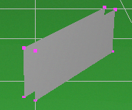
This tool is similar to Inclined rectangle. As well as the inclined rectangle it allows to place a rectangle in three-dimensional space at any angle.
After choosing this button the Loading 3D image dialog box appears. After choosing a file in *.bmp,*.jpg,*.jpeg,*.png,*.gif,*.tif or *.tiff format place 3D image in the same way as Inclined rectangle. On the Current construction parameter panel the minimal height corresponds to the bottom bound of this rectangle and the maximal height - to the top bound.
In the Graphics window the top of 3D images is displayed by thick line.
Later 3D image can be edited by moving its grips. It is possible to change 3D image sizes on the Current construction parameter panel, delete and change the image file using buttons
To make transparent pixels with color coincided with color of left bottom pixel (or transparent pixels of *.png file), check Transparence checkbox on the Current construction parameter panel.
To get the transparence of *.bmp or *.jpg file, the image file has to be specially prepared by means of any graphic editor, for example Paint. Pixels that should become transparent have to be filled by color that coincides with the color of left bottom pixel.
See also: "Constructions" button group, Materials
|
Rotakin rotates when modeling exposure time, Rolling Shutter, interlace distortions and creation of animated images.
To place the Rotakin specify a place for the Rotakin by clicking. On the current construction parameters panel it is possible to set minimal and maximal heights of the Rotakin. In the Options box it is possible to change rotation speed of all Rotakin objects.
Rotating test target named Rotakin is used in field testing of video surveillance systems by the techniques developed by the Home Office Scientific Development Branch 'Performance Testing of CCTV Perimeter Surveillance Systems (Using the Rotakin Standard Test Target) ". The Rotakin model meets the requirements of the document.
See also: "Constructions" button group
|
To place the Norman specify a place by clicking. On the current construction parameters panel it is possible to set minimal and maximal heights of the Norman.
See also: "Constructions" button group
|
The tool is designed to model illuminators with photometric accuracy.
As a result of clicking this button the Illuminator calculation box appears. You can specify internal parameters of an illuminator in the box.
See more: Illuminator calculation.
You can open the Illuminator calculation box by the
On the Line type panel it is possible to choose the line type, by which the Illuminator's icon will be drawn. Later line type can be changed using Change line type tool.
On the Current construction parameter panel it is necessary to specify Illuminator height relative to the base height of a layer to which the illuminator belongs and Inclination angle (for projectors).
See more. Current construction parameter panel> Illuminator.
After assigning the parameters in the Illuminator calculation box and on the Current construction parameter panel, specify an Illuminator place by the first clicking in horizontal projection. Then specify a radiation axis direction by the second clicking (for projectors).
If graphic specifying angle of radiation and Light intensity distribution curve (LIDC) are not required, click for the third time on any point in the graphics area. To specify angle of radiation and LIDC graphically after the second clicking clear Angle box on the Current construction parameter panel. After that by the third clicking specify angle of radiation and light intensity concentration on an axis of radiation.
It is possible to specify parameters after the Illuminator placement. To set parameters click Edit button and set parameters on the Current construction parameter panel. To open Illuminator calculation box click the In order to edit angle of radiation and concentration by moving pink grips, press and keep Ctrl pressed.
Created Illuminator will take part in 3D image modeling from some camera only if for this camera:
While modeling Illuminators VideoCAD considers only direct light. Reflected light can be considered only approximately by specifying a part of light from this Illuminator diffused on the scene. Shadows cannot be modeled in VideoCAD.
See also: Illuminator calculation, Current construction parameter panel, Built-in IR Illuminator
|
Constructions > Field-of-view size
When this button is pressed, moving the cursor in the vertical projection of graphics area a field-of-view size value passing through the cursor point is indicated on the Status bar
The field-of-view size depends on height and distance, therefore measuring in the vertical projection is allowed only.
The button is available in the graphical editing state only.
If no other measurements made after the field-of-view size is marked at a point, with changing a camera position, the values in the status bar change correspondingly, thus representing the current field-of-view sizes at a point.
See also: "Constructions" button group
|
Constructions > Test object location
When this button is pressed, clicking on the graphics area specifies the test object location. The parameters of test object location in the test object dialog box change correspondingly.
The button is available in the graphical editing state only.
See also: Test object box, 3D Test
|
Choosing this item opens a submenu enabling to switch global snaps on/off and display the snap panel, with the help of which it is convenient switch the snaps fast when drawing.
Snaps enhance the convenience in drawing. As a result of the snaps' functioning the cursor "sticks" to the certain points, lines or directions.
The snap Extension is disabled for hidden objects and in the Select/Edit mode.
In the Options box you can change snap sensitivity.
The pop-up menu appearing when clicking the graphics area with the right button of the mouse contains an item Local snap. The local snaps have the same function as the global ones though working during one operation.
|
Constructions > Lock constructions
After modeling the environment the cameras' placement stage begins. At this stage displacement of constructions is not required any more, and their casual selection can cause inconveniences. If this item is marked, the selection of constructions is locked. To release the locking, click this item once again.
|
All constructions can be not only painted, but also covered by materials (textures). Any raster images in the formats * .bmp, * .jpg, * .gif, * .tif, * .png can be used as materials. You can assign a material to a new or edited construction using the Assign Material
By selecting this menu item, you can open the Materials and License plates window on the Materials tab for editing the material library.
|
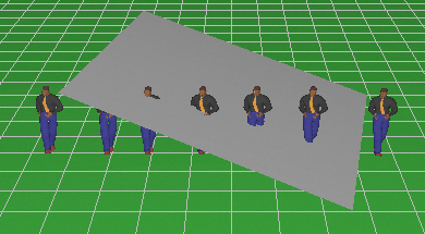
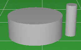
The item opens submenu, in which there are 3D models which are present in the program library.
When any item in the submenu is chosen, clicking in the graphics area specifies the place for a 3D model.
In the horizontal projection the 3D models are displayed in the top view, in the vertical projection - in the side view, and in the 3D Video and 3D World models are as 3D objects.
Horizontal and vertical projections for displaying in the Graphics window can be created in the 3D Models window.
3D models can be moved, rotated, copied, changed draw order as other VideoCAD objects.
The default height of the 3D models above the ground is determined by the maximal height of the line type which was chosen when the 3D model was being placed. The height can be set separately for each 3D model using the current construction parameters panel.
To change 3D model height above the ground, select the 3D model, then change line type or switch the 3D model to editing state by double clicking on it and change value in the 3D H box on the Current construction parameters panel.
By default the 3D models are on the ground and constructed by the line type with the number, specified on the Lines tab of the Options box. This line type has the maximum height equal to 0. Heights can also take on negative values, in this case 3D model plunges under ground. For example, to place a 3D model on a surface: construct the surface by the rectangle tool using line type with the required maximum height, place the 3D model on it, and then change 3D model line type to the line type of the surface.
In multilevel 3D projects heights are calculated relative to the base height of a layer the which the 3D model belongs. By changing the base height a layer you can move up or down all 3D models and constructions on the layer
In the Editing state using the Current construction parameters panel you can resize 3D models separately on axes. To do this, enter new values into X, Y, Z boxes during 3D model editing. If the
You can see how any 3D model will look at any point in space through the active camera using the 3D Test and 3D Test on View area bounds tools.
See also: 3D Video, 3D World, 3D Models, Options box>Lines, Options box>3D modeling.
|
Open the 3D Models window. This window is intended for working with 3D models, add, delete, duplicate, make projections etc.
See more: 3D Models window
|
3D models > Add 3D model (*.vcm,vbm)
Add a 3D model to the program library. In the dialog box, select a file of 3D model *. vcm or *.vbm format and click Open.
*.vbm and *.vcm files can be obtained by saving in the 3D Models window. Files in *.vcm format can be obtained by exporting from SketchUP using the free plugin.
See more: Import of 3D models, 3D Models window
If your 3D model has textures, in the same directory where the *.vcm (*.vbm) file is opened from, a folder with textures must be. The folder should be named <model name> _textures. VideoCAD plugin for SketchUP automatically creates the folder with the textures in the directory of saving exported model.
|
3D models > Import 3D model (*.dae,3ds,obj...)
Import a 3D model from a file.
After clicking on this item, select the 3D model file. After reading the file, the 3D Models window and the Import 3D Models panel appear, on which you can transform the imported model, cut out a part from it, add a license plate and change the import options. If you do not need to change the model, just click OK in the Import 3D Model panel.
See more: Import of 3D models, 3D Models window, Import 3D Models panel
|
3D models > 3D model from selection
Create a 3D model from selected constructions and 3D models.
The item is enabled when there are selected constructions or 3D models.
After creation of the model, the 3D Models window and the Import 3D Models panel appear, on which you can transform the imported model, cut out a part from it, add a license plate and change the import options. If you do not need to change the model, just click OK in the Import 3D Model panel.
This tool allows limited editing 3D models from VideoCAD library. To supplement a 3D model, combine several 3D models, apply tools from the Import 3D Models panel to the model (for example, cutting out parts):
See more: Import of 3D models, 3D Models window, Import 3D Models panel
|
3D models > Export selection to 3D file COLLADA
Export to COLLADA works only in VideoCAD Professional.
Export a scene with selected cameras, constructions and 3D models to a 3D file COLLADA (* .dae). COLLADA files can be imported by many 3D editors including SketchUP.
See more about COLLADA file https://en.wikipedia.org/wiki/COLLADA VideoCAD can also import COLLADA files.
Before exporting, select what you want to export. The export may take a long time depending on the quantity of exported. To estimate the time, try exporting something simple first. Constructions, 3D models and cameras are exported exactly as they appear in the 3D World window. Before exporting, you can adjust the overall transparency of the borders in the settings of the 3D World window. The file also includes layer information and camera names, but not all programs read this information.
The export will result in a *.dae file and a folder with textures with the same name as the file. Transfer the received COLLADA file along with this folder.
To display the resulting file in SketchUP without black lines on the edges, hide the edges and boundaries of the polygons by unchecking the View> Edge Style> menu.
In the Options box> Export> 3D COLLADA you can configure export parameters.
See also: Import of 3D models, 3D Models window, Import 3D Models panel
|
By default, the same default license plate is displayed on all 3D models - cars. It is possible to assign another license plate to the 3D Model using the Assign License plate
As the license plates any raster images in the formats * .bmp, * .jpg, * .gif, * .tif, * .png can be used.
By selecting this menu item, you can open the Materials and License plates window on the Plates tab for editing the License plate library
|
3D models > Default license plate
Open the 3D modeling tab of the Options box. On the tab you can see the license plate used by default for 3D models, 3D Tests and test images in the Pixel density box.
To change the default license plate, click on it's image.
Except the default license plate, you can set special license plates for the placed or edited 3D models You can add license plates, set their position on 3D models in the 3D Models window.
|
Select all constructions, models, cameras, cables and illuminators on the current layout.
|
If Ctrl is pressed at clicking, the objects within the selection window are inverted, on the contrary, state of those not hitting in the selection window remains the same.
If at the moment of the second click the Shift key is pressed, then not only objects that get into the selection window as a whole, but also partially getting objects will invert its selection state.
It is possible to select objects by one by clicking their image once, thus enabling the earlier selected objects to revert to normal state. If Ctrl is pressed at clicking, the objects are inverted, and the state of the rest remains the same. Using the
Using the Selection Editing Panel, you can change the same type of parameters at once of all selected objects.
You can make a 3D model insensitive to mouse click by Lock checkbox in the 3D Models window.
During construction 3D scenes it is often necessary to place some constructions one over another at a different height, made by means of different line types. To select one or more construction, located one over another, made by means of different line types:
select the construction by clicking.
Just repeat clicking at the same place without moving the cursor. Thus objects under the cursor will be selected sequentially.
Layers are very useful for multi-level constructions.
An object can be inaccessible for selection if it belongs to a not enabled layer. A camera may be not available for selection if it belongs to an inaccessible group of cameras or is on an inaccessible layer.
To move objects on the foreground or background use menu items: Bring to front, Send to back.
Selected objects can be moved. To move the selected objects, bring the cursor to the selected one, press the left mouse button and move the selected objects. After finishing the moving, release left mouse button. If you hold Ctrl while releasing the button, copying will take place instead of moving.
To cancel selection click this button again.
To select all objects on the current layout use Ctrl+A shortcut.
For switching to Select / Edit mode from any mode use also Esc button.
See also: Selected state
See also: "Edit" button group
|
Cut the selected objects into the VideoCAD internal clipboard.
It is possible to cut objects of different projections at a time, and to cut any quantity of constructions, 3D objects, cameras, illuminators, texts and cables.
When cutting the Active camera it is copied.
See also: Cut with base point.
|
Copy the selected objects into the VideoCAD internal clipboard.
It is possible to copy objects of different projections at a time, and to copy any quantity of constructions, 3D objects, illuminators, texts and cables. If you hold Ctrl while moving, then copying will take place instead of moving.
See also: Copy with base point.
|
Cut the selected objects into the VideoCAD internal clipboard relative to a base point. After clicking this button specify the base point of cutting.
It is possible to cut objects of different projections at a time, and to cut any quantity of constructions, 3D objects, texts, cameras, illuminators and cables as well.
When cutting the active camera it is copied.
See also: Cut.
|
Copy the selected objects into the VideoCAD internal clipboard relative to a base point. After clicking this button specify the base point of copying.
It is possible to copy objects of different projections at a time, and to copy any quantity of constructions, 3D objects, texts, cameras, illuminators and cables as well.
See also: Copy.
|
Paste the objects from the VideoCAD internal clipboard. After clicking this button specify the base point of paste in the projection being clicked when cutting or copying.
It is possible to paste into different layouts, paste cables of one camera while another camera is active (in this case the pasted cables belong to a camera which is active during paste), and to paste any quantity of constructions, 3D objects, cameras, illuminators, texts and cables at a time.
Be careful when copying and pasting cables. You can copy only cables of Active camera, and when pasting, these cables will belong to the camera which is active during pasting.
If a camera is being pasted a new camera with parameters of the pasted camera is created automatically. This is an alternative way to create new cameras.
Shadows in the Graphics window and in the 3D World are calculated for the active camera, but pasted camera doesn't become active. Therefore the view area of the pasted camera is displayed without shadows. To calculate shadows - activate the camera after pasting.
Pasting is always performed to the active layer. At the moment of placing new camera or pasting copied camera, its base height is set to the base height of the active layer.
See also: How to copy constructions and 3D models to another project.
|
Move the selected objects. After clicking this button the first click in a graphics area designates the starting moving point, the second click - the final one. If you hold Ctrl at the moment of the second click, then copying will take place instead of moving.
When moving take into account the projection to which the objects are attached. A simultaneous moving objects in different projections vertically is locked as being incorrect.
Selected objects or cameras can be moved in Select / edit mode. In order to move place the cursor above the selected object, press left mouse button, move, after moving is finished release the left mouse button. If you hold Ctrl while releasing the button, copying will take place instead of moving.
Shadows in the Graphics window and in the 3D World are calculated for the active camera, but moved camera can be not active. If the camera is not active, the view area of the moved camera is displayed with old shadows. To recalculate shadows - activate the camera after moving.
|
Rotate the selected objects. After clicking this button the first click in a graphics area designates the rotation center, the second click specifies the initial rotating point, and the third click specifies the final rotating point.
When rotating take into account the projection to which the objects are attached. The selected objects, attached to the projection with a rotation center designated, can rotate only.
The scalable fonts can rotate only. If a font is not scalable then its initial point rotates only, the text remaining horizontal.
The active camera can be rotated in Select / edit mode by moving the grip in the middle of the view area upper bound.
Shadows in the Graphics window and in the 3D World are calculated for the active camera, but rotated camera can be not active. If the camera is not active, the view area of the rotated camera is displayed with old shadows. To recalculate shadows - activate the camera after rotating.
|
Change scale of selected constructions relative to the center of scaling.
After clicking on this button, the first click on the graphics area specifies the center of scaling.
Then moving the cursor up increases sizes of selected constructions, moving the cursor down decreases sizes of selected constructions.
In the Status bar the current scale factor is displayed.
When required sizes will be achieved, click for the second time to complete scaling operation. To cancel the scaling press ESC.
This tool does not scale 3D models. 3D models can be scaled in editing state with the help of the Current construction parameter panel.
|
Mirror the selected constructions relative to the horizontal or vertical line passing through the specified point.
After clicking on this button, the first click on the graphics area specifies the point through which a mirror line must be passed.
Then moving the cursor changes position of the mirror line.
When required position of the mirroring objects will be achieved, click for the second time to complete mirroring operation. To cancel mirroring press ESC.
|
The Selection filter allows you to quickly filter selected objects and cameras by many features and their combinations: type of construction or 3D models, camera models, lens focal lengths and camera resolutions, layers, line types, color in 2D and 3D, materials.
You can filter only objects that fit fully or partially within the specified range of heights. The range of heights can be measured from Zero ground (taking into account the heights of the layers on which the objects are located) or without taking into account the heights of the layers.
When this tool is selected, the Selection Filter panel appears. The panel contains drop-down windows in which lists of types of currently selected objects with marks appear. To filter the selection, leave marks only on the objects that you want to keep selected and click Apply or double-click on any window.
If the Keep filter checkbox is checked, the configured filter will be stored between selection operations. To work with the panel, you can also use the panel's pop-up menu.
The panel can be stretched with the mouse over the edge.
Together with the Selection Editing Panel, this tool provides great opportunities for group operations for quick and easy editing VideoCAD projects.
|
Move selected objects on the foreground, then other objects will not shadow them. To move cameras over constructions use the Cameras over constructions item.
Changing the objects' draw order can be required at operation with large 3D models of rooms, and also at operation with constructions placed one over another.
|
Move selected objects on the background, then selected objects will be covered by other objects. To move cameras over constructions use the Cameras over constructions item.
Changing the objects' draw order can be required at operation with large 3D models of rooms, and also at operation with constructions placed one over another.
|
Hide the selected objects.
With this item chosen the selected objects proceed into hidden state. In the hidden state the objects in the Graphics window are displayed on the background in light grey color. The rest characteristics are similar to those of normal state.
In the 3D World and 3D Video windows the hidden objects are not displayed. Hidden objects are not exported to AutoCAD formats, therefore to exclude some objects from export - hide them.
The hidden state is used to conceal the temporarily interfering objects.
To return to normal state select the hidden objects.
The snap Extension is disabled for hidden objects.
When working with a separate object it is convenient to select all the objects in layout using the shortcut Ctrl+A and hide them. After that select the objects needed.
See also: Layer - Hidden;
|
Align the selected objects.
Because limited accuracy of computer calculations, sometimes after a rotation objects' form is being distorted a little. The effect of choosing this item is alignment of the form of selected objects.
Efficiency of alignment depends on a scale. Vast scale provides the minimum of efficiency, small scale - the maximum. At high degree of efficiency small objects can be distorted.
|
After choosing this item at the bottom of the graphics area appears the line type panel. In the line type panel you can choose line type for the selected constructions and cameras.
If you hold down Ctrl while changing the line type of editing construction (constructions), the colors, as well as the minimum and maximum heights of the construction will become equal to the parameters set in the new line type. If Ctrl is not pressed, the colors and heights of the editing construction (constructions) will not change.
For changing line type use the Line type panel in editing state.
|
Combine to a block all selected constructions. The block will behave as one object. Combining is convenient at modeling complex objects and their subsequent moving, rotating and copying. To destroy the block use the Destroy tool.
|
Merge contours of selected constructions. This tool works with walls and rectangles. Merging improves appearance of drawing of buildings. To destroy merged contours use the Destroy tool.
Line type of the contour is determined by line type of the first construction of the contour. You can create multiple contours of different constructions with different line types.
|
Switch ON selected illuminators.
For one camera no more than 7 illuminators could be switched on simultaneously (including Built-in IR Illuminator). Switched on illuminators are saved in camera parameters, therefore it is possible to switch on and switch off different illuminators for each camera.
|
Edit > Switch OFF illuminators
Switch OFF selected illuminators.
|
Undo the last operation.
VideoCAD stores several last operations including Undo operation. When clicking this button successively VideoCAD retraces to the last states and a state before the button Undo was clicked for the first time. The quantity of the stored operations can be adjusted in the Options box>Miscellaneous>UNDO depth.
|
Redo the last operation undone by the UNDO tool.
|
Erase the selected objects.
If there are no selected objects this item is disabled.
Use also Del.
You can not erase the active camera.
|
Erase all constructions.
If there are no constructions this item is disabled.
|
When this button pressed, you can draw the signal cable of the active camera by successive clicks in the graphics area. The end of each segment is the start of the next one. To stop drawing cable, press ESC.
The status bar displays the segment length and its projection to distance and height.
Both clicks are to be made in the same projection. If the projections are different the measured values are incorrect, therefore when constructing a segment with its ends in different projections the values are not displayed in the status bar. In this case when changing the drawing the segment is attached to the projection with its initial point.
A cable consists of segments, allowing to draw it in different projections and layouts, representing an actual scheme of laying accurately.
When copying the cable segments between cameras and layouts a process of cable drawing is accelerated considerably even in complex CCTV systems.
When drawing a cable the menu item Cable laying might be used. When choosing it a float panel of the same name appears enabling to choose a shift of segment ends for a level parallel cable drawing along the walls, columns etc.
The type and parameters of line designating the Signal cable can be changed in the options box.
VideoCAD summarizes the lengths of all the segments, considers the reserves and calculates the total length of cable. To change the default parameters and obtain the calculation results double-click the image of any cable segment or click Signal cable again. A dialog box of the same name appears after that. You can open this box by choosing Calculate item near Signal cable item.
The results of the cables' calculation on each individual camera and on the project as a whole are included into the text file obtained by Text report, Table of cameras and Cable report.
In multi-layer drawings, cables belong to the same layer as a camera to which the cables belong.
It is possible to use Line segments for cable modeling with subsequent cable length calculation. Use separate line types for drawing a cable of each type. For length calculation use the Length calculation of line segments tool and the Cable report.
See also: "Constructions" button group, View>Active camera cables, View>All camera cables, Cable laying, Length calculation of line segments, Cable report.
|
When this button pressed, you can draw the power cable of the active camera by successive clicks in the graphics area. The end of each segment is the start of the next one. To stop drawing cable, press ESC.
The status bar displays the segment length and its projection to distance and height.
Both clicks are to be made in the same projection. If the projections are different the measured values are incorrect, therefore when constructing a segment with its ends in different projections the values are not displayed in the status bar. In this case when changing a drawing the segment is attached to the projection with its initial point.
A cable consists of segments, allowing to draw it in different projections and layouts, representing an actual scheme of laying accurately.
When copying the cable segments between cameras and layouts a process of cable drawing is accelerated considerably even in complex CCTV systems.
When drawing a cable the menu item Cable laying might be used. When choosing it a float panel of the same name appears enabling to choose a shift of segment ends for a level parallel cable drawing along the walls, columns etc.
The type and parameters of line designating the power cable can be changed in the options box.
VideoCAD summarizes the lengths of all the segments, considers the reserves and calculates the total length of cable. To change the default parameters and obtain the calculation results double-click the image of any cable segment or click Power cable again.
A dialog box of the same name appears after that enabling to choose a cross-section area of power cable to fit the requirements of camera voltage supply. It is assumed that the conductor material is copper and the conductor temperature is + 50° C You can open this box by choosing Calculate item near Power cable item.
The results of the cables' calculation on each individual camera, each individual section area and on the project as a whole are included into the text file obtained by Text report, Table of cameras and Cable report.
In multi-layer drawings, cables belong to the same layer as a camera to which the cables belong.
It is possible to use Line segments for cable modeling with subsequent cable length calculation. Use separate line types for drawing a cable of each type. For length calculation use the Length calculation of line segments tool, Cable report.
See also: "Constructions" button group, View>Active camera cables, View>All camera cables, Cable laying, Length calculation of line segments, Cable report.
|
With this item chosen a float panel of the same name appears enabling to choose a shift of segment ends for a level parallel cable drawing along the walls, columns etc.
See also: View>Active camera cables, View>All camera cables
|
Cables > Length calculation of line segments
Clicking this item will open a box allowing calculate total length of any line segments. This tool allows using line segments for modeling cables.
See more: Length calculation of line segments, See also: Cables
|
Choosing this item opens a box with a text report of all line segments and cables made by line types with marked Cable box in the parameters of the line type. These line types are considered as cable brands. These line types can be assigned to the Signal cable and the Power cable of any camera.
You can simply draw cables as line segments on layouts using these line types. In this case, the cables are considered as main cables which are not attached to any camera.
The Cable report includes the cables attached to cameras and the main cables as well. Cable lengths is calculated for each brand (line type) separately.
See also: Length calculation of line segments, Calculation lenght of cables and getting the Cable report, Signal cable length calculation box, Power cable electrical parameters and length calculation box, Table of Cables, Table of Cables in PDF Report.
|
Criteria > Person detection area
Display a box with the person detection criteria.
See more: Criteria editing box of person detection area
|
Criteria > Person identification area
Display a box with the person identification criteria.
See more: Criteria editing box of person identification area
|
Criteria > License plate reading area
Display a box with the license plate reading criteria.
See more: Criteria editing box of license plate reading area
|
Open a box to edit the quality levels. This box allows to edit quality level criteria values and assign a quality level to the active camera.
See more: Quality level box |
Open the About box with the general information of VideoCAD version and the Authors.
|
Open the contents of this Help file.
|
Choose the language.
All the text resources of the program are stored in *.lng files in the VideoCAD installation directory. We are interested in translating the program to other languages. If you can do it, could you please contact us.support@cctvcad.com
We offer big discounts for the translations.
As all text strings are kept in the *.lng files, you can change any texts in the program by editing these files. Just find a string that you want to change and edit it.
|
Help > Check the latest version
Check the latest version of VideoCAD on the developer's web site.
Checking the latest version is also performed automatically when the program starts. When an update is found, the information box appears.
If a box with information about the latest version does not appear, but you can open cctvcad.com in your browser, then VideoCAD cannot connect to the Internet from your computer. In this case, contact your system administrator to allow this connection. You may need a password for the proxy server on your local network. See more: Internet.
|
Visit CCTVCAD Software home page in the Internet.
|
Visit CCTVCAD Software Order page in the Internet.
|
Visit CCTVCAD Software User forum in the Internet.
|
Send us an email message.
|
Help > Change registration code
The program will stop, a box for entering a new registration code will appear at the next VideoCAD start.
The ability to change the registration code is required for users of multiple licenses with USB dongle. Each USB dongle has its own registration code. The message at startup "The Dongle does not fit the License." means that the USB dongle does not match the code with which the program is registered. You must either change the USB dongle or enter the code corresponding to the connected dongle.
In case of a license without USB dongle, it may be necessary to change a temporary registration code to a permanent one or to another temporary code.
ATTENTION USERS OF LICENSE WITHOUT USB DONGLE!
Changing the registration code by this item removes the license from the computer without releasing the license on the server. The license remains bound to this computer and cannot be activated on another computer. To transfer the license to another computer, do not change the registration code, but uninstall VideoCAD from this computer and install it on a new computer. Uninstalling releases the license on the server.
This item is hidden in the demo-version.
|